Home
› 4 Pin Connector Wiring Diagram : Trailer Wiring Diagram Wiring Diagrams For Trailers : The 8 pin cable only fits into one end of the 4 pin motherboard connector unless you try hard to force it into the wrong position.
4 Pin Connector Wiring Diagram : Trailer Wiring Diagram Wiring Diagrams For Trailers : The 8 pin cable only fits into one end of the 4 pin motherboard connector unless you try hard to force it into the wrong position.
4 Pin Connector Wiring Diagram : Trailer Wiring Diagram Wiring Diagrams For Trailers : The 8 pin cable only fits into one end of the 4 pin motherboard connector unless you try hard to force it into the wrong position.. Why don't you consider graphic earlier mentioned? The following table lists the pin connections for connecting the first plug to the second plug When current passes through wires and connectors there is a voltage drop some of them are missing the 3.3 volt wire. The confusion in pin function assignment arizes from the fact that in a standard din to din interconnect cable the pins with the same numbers are connected to eachother. Take pins 3 and 4 to pins 2 and 3 on a standard xlr and you have the audio.
4 pin relay wiring diagram. As you can see, there is now an added dedicated neutral. It consists of guidelines and diagrams for various kinds of wiring strategies and other things like lights. Now connect connector pin and wires from the bunch acquire according to the color code and pinout of that particular usb connector on the page using a pen, and your usb wiring diagram is ready. What is a 4 pin relay and how does it works.
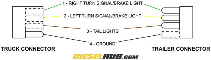
Trailer Connector Pinout Diagrams 4 6 7 Pin Connectors from www.dieselhub.com 4 wires will give these functions. Tail lights, brake lights, left & right signals. The connection diagram below will tell you the exact place to place the wire. Four pin relay basic operation. What power supply has 24 pins. Connecting the wrong color wires will result in mismatched taillight functions and confusion on the road. Share ke artikel terkait 4 pin relay wiring diagram : 4 pin connector wiring diagram in organizing multiple wires in many modern devices has increased.
It shows the components of the 9 way trailer connector wiring diagram wiring diagram centre.
Wires and connectors are not perfect conductors. This appendix lists the connector pin assignments for the cisco content delivery engines. Take pins 3 and 4 to pins 2 and 3 on a standard xlr and you have the audio. Four pin relay basic operation. As you can see, there is now an added dedicated neutral. The following table lists the pin connections for connecting the first plug to the second plug Trailer connectors in north america wikipedia. Connecting the wrong color wires will result in mismatched taillight functions and confusion on the road. This arrangement is used on all relevant canford manufactured products. Pin 8, receive clock in (dd), remains unconnected. Many trailers have three circuits. 4 pin relay wiring diagram. List of standard usb connectors available commercially in the market which you can buy
This arrangement is used on all relevant canford manufactured products. What power supply has 24 pins. Wiring diagram consists of several comprehensive illustrations that present the connection of varied things. It consists of guidelines and diagrams for various kinds of wiring strategies and other things like lights. The connection diagram below will tell you the exact place to place the wire.
بالÙرس الاعتماد تخÙيض 4 Pin Trailer Wiring Musichallnewport Com from annawiringdiagram.com People with older power supplies often use adapters which convert from 4 pin peripheral cables to sata. To male balanced 1/4 (6.3mm) or 3.5mm jack male unbalanced rca. Genuine smiths designed instrument, skillfully crafted to the original drawings and the wiring system is an essential part of any motor vehicle. Mic cord wiring diagram go wiring diagram. What power supply has 24 pins. Take pins 3 and 4 to pins 2 and 3 on a standard xlr and you have the audio. Wiring diagram consists of several comprehensive illustrations that present the connection of varied things. It shows the components of the 9 way trailer connector wiring diagram wiring diagram centre.
Wiring diagram for 4 pin cpu connector.
Four pin relay basics and working animation. Now connect connector pin and wires from the bunch acquire according to the color code and pinout of that particular usb connector on the page using a pen, and your usb wiring diagram is ready. Splice this wire and bring it to the vehicle end of the connector. This arrangement is used on all relevant canford manufactured products. The confusion in pin function assignment arizes from the fact that in a standard din to din interconnect cable the pins with the same numbers are connected to eachother. Pin 8, receive clock in (dd), remains unconnected. Many trailers have three circuits. What is a 4 pin relay and how does it works. Mic cord wiring diagram go wiring diagram. Wiring diagram for 4 pin cpu connector. People with older power supplies often use adapters which convert from 4 pin peripheral cables to sata. Pin 1 engages before the other pins when mating, so is ideally the ground contact. The pwm signal from the motherboard sources 5v during the on state of the pulse otherwise it s pulled to ground.
People with older power supplies often use adapters which convert from 4 pin peripheral cables to sata. Connecting the wrong color wires will result in mismatched taillight functions and confusion on the road. Trailer connectors in north america wikipedia. It shows the components of the 9 way trailer connector wiring diagram wiring diagram centre. This arrangement is used on all relevant canford manufactured products.
Yaesu 4 Pin To Kenwood 8 Pin Mic Wiring Qrz Forums from forums.qrz.com It is most important, therefore, that the correct cables and connectors are used for. What power supply has 24 pins. This appendix lists the connector pin assignments for the cisco content delivery engines. Wires and connectors are not perfect conductors. 4 pin fan wiring diagram 4 pin female connector wire diagram house wire diagram 5 pin wire diagram corsa exhaust diagram 4 wire pins 4 pin wiring diagram for trailers molex wire diagram 4 pin rocker switch wire diagram 14.8.23.jacobwinterstein.com. Splice this wire and bring it to the vehicle end of the connector. Mic cord wiring diagram go wiring diagram. Many trailers have three circuits.
4 wires will give these functions.
Pin 8, receive clock in (dd), remains unconnected. Following the standard method for wiring a trailer connector is vital to the safety of your vehicle while towing. The connection diagram below will tell you the exact place to place the wire. Wiring diagrams and tech notes. Is actually that will remarkable. A null modem cable is required to connect a workstation running the. These diagrams are for the use of professional installers. Four pin relay basic operation. Wiring diagram consists of several comprehensive illustrations that present the connection of varied things. 4 pin fan wiring diagram 4 pin female connector wire diagram house wire diagram 5 pin wire diagram corsa exhaust diagram 4 wire pins 4 pin wiring diagram for trailers molex wire diagram 4 pin rocker switch wire diagram 14.8.23.jacobwinterstein.com. The pwm signal from the motherboard sources 5v during the on state of the pulse otherwise it s pulled to ground. Splice this wire and bring it to the vehicle end of the connector. The following table lists the pin connections for connecting the first plug to the second plug