Circuit Diagrams Explained - Difference Between Schematics And Circuit Diagrams / Read more about this circuit. Electric circuits like ac lighting circuit, battery charging circuit, energy meter, switch circuit, air conditioning circuit, thermocouple circuit, dc lighting circuit, multimeter circuit, current transformer circuit, single phase motor circuit are explained with diagrams. A mosfet works similar to the npn transistor, but with one important difference: Getting from point a to point b. Integrated circuits integrated circuits accomplish such unique tasks, and are so numerous, that they don't really get a unique circuit symbol. Schematic electrical wiring diagrams are different from other electrical wiring diagrams because they show the flow through the circuit rather than the physical layout of any equipment.
When the switch is off, a complete circuit will not exist, and there will be no current. Circuit breaker control schematic explained Getting from point a to point b. Create circuit diagram with ease. An electrical wiring diagram could be a single page schematic of how a ceiling fan should be connected to the power source and its remote switches.
Circuit Symbols Electronics Club from electronicsclub.info When and how to use a wiring diagram Symbol usage depends on the audience viewing the diagram. Electric circuit diagrams often have more or different parts shown using symbols. The home electrical wiring diagrams start from this main plan of an actual home which was recently wired and is in the final stages. Circuit diagrams or schematic diagrams show electrical connections of wires or conductors by using a node as shown in the image below. Schematic diagrams should be arranged for simplicity and ease of understanding without regard for the actual physical location of any component, only focusing on how they connect together. This circuit may make laughter. So easy to builds and inexpensive!
Schematic electrical wiring diagrams are different from other electrical wiring diagrams because they show the flow through the circuit rather than the physical layout of any equipment.
Another fine example of nerd sniping, as mentioned in the title text.there are pieces of circuit diagrams, road maps, chemical diagrams, and other things all mixed in. The home electrical wiring diagrams start from this main plan of an actual home which was recently wired and is in the final stages. Read more about this circuit A wiring diagram may include the wirings of a vehicle. These two different types of circuit diagrams are called pictorial (using basic images) or schematic style (using industry standard symbols). A mosfet works similar to the npn transistor, but with one important difference: In the mosfet transistor, the voltage between gate and source decides how much current can flow from drain to source. A circuit diagram (also known as an electrical diagram, elementary diagram, or electronic schematic) is a simplified conventional graphical representation of an electrical circuit.a pictorial circuit diagram uses simple images of components, while a schematic diagram shows the components of the circuit as simplified standard symbols; Getting from point a to point b. Also called wiring diagrams or circuit diagrams, these diagrams show how the different components of a circuit are connected. A circuit diagram (electrical diagram, elementary diagram, electronic schematic) is a graphical representation of an electrical circuit. For example, how the horns are powered and connected to the controller on your steering wheel. This instructable will show you exactly how to read all those confusing circuit diagrams and then how to assemble the circuits on a breadboard!
For example, how the horns are powered and connected to the controller on your steering wheel. Dc circuit and electrical power review. Here i have given the circuit diagram of electronic ballast with proper indication and explained each part of the circuit. The purpose is the same: A pictorial circuit diagram uses simple images of components, while a schematic diagram shows the components and interconnections of the circuit using standardized symbolic representations.
Electrical Circuit Basics 12 Volt Planet from www.12voltplanet.co.uk A node is simply a filled circle or dot. Getting from point a to point b. Integrated circuits integrated circuits accomplish such unique tasks, and are so numerous, that they don't really get a unique circuit symbol. Dc circuit and electrical power review. Circuit breaker control schematic explained These two different types of circuit diagrams are called pictorial (using basic images) or schematic style (using industry standard symbols). A beginner's guide to circuit diagrams november 4, 2014 by author a first look at a circuit diagram may be confusing, but if you can read a subway map, you can read schematics. In the npn transistor, the current from base to emitter decides how much current can flow from collector to emitter.
Symbol usage depends on the audience viewing the diagram.
Integrated circuits integrated circuits accomplish such unique tasks, and are so numerous, that they don't really get a unique circuit symbol. A circuit diagram is a visual display of an electrical circuit using either basic images of parts or industry standard symbols. Electric circuit diagrams often have more or different parts shown using symbols. It shows the relative positions of all the elements and their connections to one another. A pictorial circuit diagram uses simple images of components, while a schematic diagram shows the components and interconnections of the circuit using standardized symbolic representations. To be able to read and understand an electric circuit diagram, you need to know the different parts and the symbols. Literally, a circuit is the path that allows electricity to flow. Each block is a complicated circuit that can be explained using other drawing techniques described below. The output is low current. A schematic is best described as an impression of the circuit and wiring than a genuine representation. Remember, battery power (voltage) at the top of the page is trying to get to the ground at the bottom of the diagram. A node is simply a filled circle or dot. This circuit may make laughter.
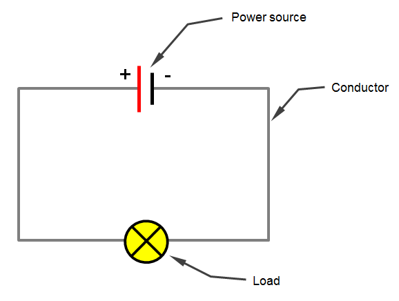
Schematic diagrams should be arranged for simplicity and ease of understanding without regard for the actual physical location of any component, only focusing on how they connect together. The important components of typical home electrical wiring including code information and optional circuit considerations are explained as we look at each area of the home as it is being wired. An electrical wiring diagram could be a single page schematic of how a ceiling fan should be connected to the power source and its remote switches. The diagram above shows a simple circuit of a flashlight with a battery at one end and a flashlight bulb at the other end. It is often used to provide a visual representation of the circuit to an electrician.
Wiring Diagram Wikipedia from upload.wikimedia.org Getting from point a to point b. A schematic is best described as an impression of the circuit and wiring than a genuine representation. It shows how the electrical wires are interconnected and can also show where fixtures and components may be connected to the system. The diagram below is a basic car light circuit, at first sight it might look complicated, but as you understand the flow, it will become clear. Here i have given the circuit diagram of electronic ballast with proper indication and explained each part of the circuit. When the switch is on, there will be a complete circuit and a flow of current resulting in the flashbulb emitting light. Usually, an integrated circuit is represented by a rectangle, with pins extending out of the sides. Pneumatic circuit symbols representing these valves provide detailed information about the valve they represent.
Templates, tools & symbols for any circuit diagram or design.
After seeing a few circuit diagrams, you'll quickly learn how to distinguish the different symbols. Here is a brief breakdown of how to read a symbol. Templates, tools & symbols for any circuit diagram or design. A circuit diagram is a visual display of an electrical circuit using either basic images of parts or industry standard symbols. When the switch is off, a complete circuit will not exist, and there will be no current. A mosfet works similar to the npn transistor, but with one important difference: It shows how the electrical wires are interconnected and can also show where fixtures and components may be connected to the system. Here i have given the circuit diagram of electronic ballast with proper indication and explained each part of the circuit. For example, how the horns are powered and connected to the controller on your steering wheel. Create circuit diagram with ease. In the npn transistor, the current from base to emitter decides how much current can flow from collector to emitter. The diagram above shows a simple circuit of a flashlight with a battery at one end and a flashlight bulb at the other end. Also called wiring diagrams or circuit diagrams, these diagrams show how the different components of a circuit are connected.