Wiring Diagram Required For Zone 1 : Aswc 1 Wiring Diagram | Free Wiring Diagram / 1 applicant information required for all applications.. The original owner did not keep his stereo after he. Wiring diagram for single pir detector on a single zone. When overall connections are required, see the overall electrical wiring diagram at the end of this. Logic diagram for 81 mux you can observe that the input signals are d0 d1 d2 d3 d4 d5 d6 d7 s0 s1 s2 and the output signal is out. It shows the components of the circuit as simplified shapes, and the power and signal connections between the devices.
Alarm device wiring diagrams (1). Please note that these drawings reflect the standard configuration. When overall connections are required, see the overall electrical wiring diagram at the end of this. It shows the components of the circuit as simplified shapes, and the power and signal connections between the devices. Download wiring diagrams for floor units, ceiling units, in row units, gpod units, heat exchangers and system controls.
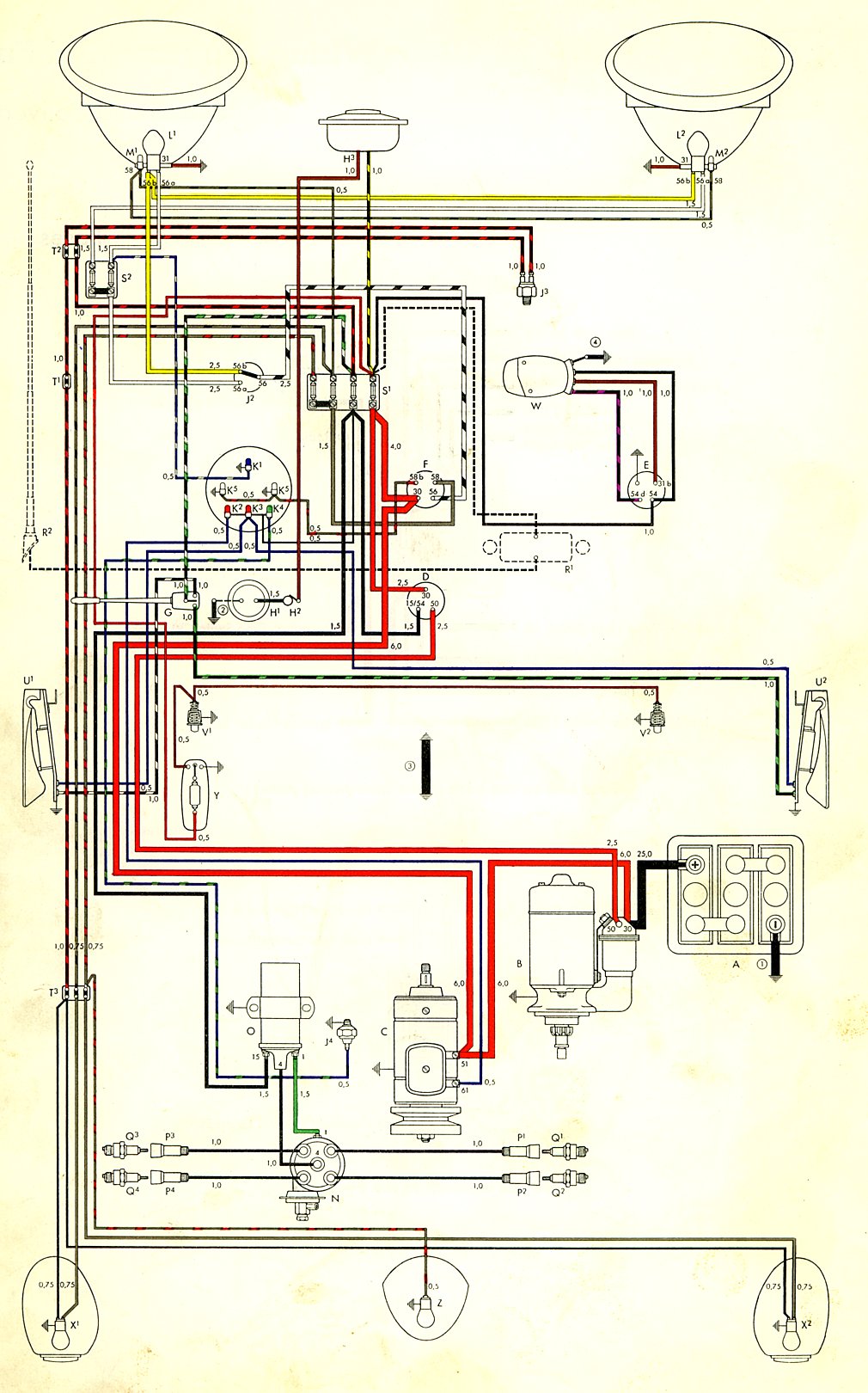
TheSamba.com :: Type 1 Wiring Diagrams from www.thesamba.com Electric motor that has a great horse power would require a large initial torque in order to fight the inertia and load diagram below will give you a new experience for those who want to learn how to rewinding induction motors in accordance with the following specifications. Wiring diagram for two pir detectors to a single zone. For wire sizes, also see wiring size conversion chart. Logic diagram for 81 mux you can observe that the input signals are d0 d1 d2 d3 d4 d5 d6 d7 s0 s1 s2 and the output signal is out. If your running a new circuit, i highly. The 3 prong dryer wiring diagram here shows the proper connections for both ends of the circuit. Right click on the diagram/key/fuse box you want to download. Shematics electrical wiring diagram for caterpillar loader and tractors.
Heating zone valve wiring & manuals manuals & diagrams:
Internal wiring for each junction block is also provided for better understanding of connection within a junction block. For mounting and wiring the sensors, see the carrier sensors. The 3 prong dryer wiring diagram here shows the proper connections for both ends of the circuit. Without first consulting your local. Electric motor that has a great horse power would require a large initial torque in order to fight the inertia and load diagram below will give you a new experience for those who want to learn how to rewinding induction motors in accordance with the following specifications. The article also contains the purpose and benefits of creating a type of wiring diagram wiring diagram vs schematic diagram how to read a wiring diagram: Wiring the vvt zone controller for power. Print or download electrical wiring & diagrams. 1 applicant information required for all applications. When and how to use a wiring. Logic diagram for 81 mux you can observe that the input signals are d0 d1 d2 d3 d4 d5 d6 d7 s0 s1 s2 and the output signal is out. It shows how the electrical wires are interconnected and can also show where fixtures and components may be connected to the system. The daq board supports input voltages from 5 v to 50 v, and output voltages from 5 v to 40 v.
Data alarm processor 4 (dap4). Electrical schematic & wiring diagrams. If you cannot find the wiring diagram you require, contact us during our opening hours for further assistance. Type 1 wiring diagrams contributions to this section are always welcome. If you are not sure how to properly wire the device, consult the advantech manual.
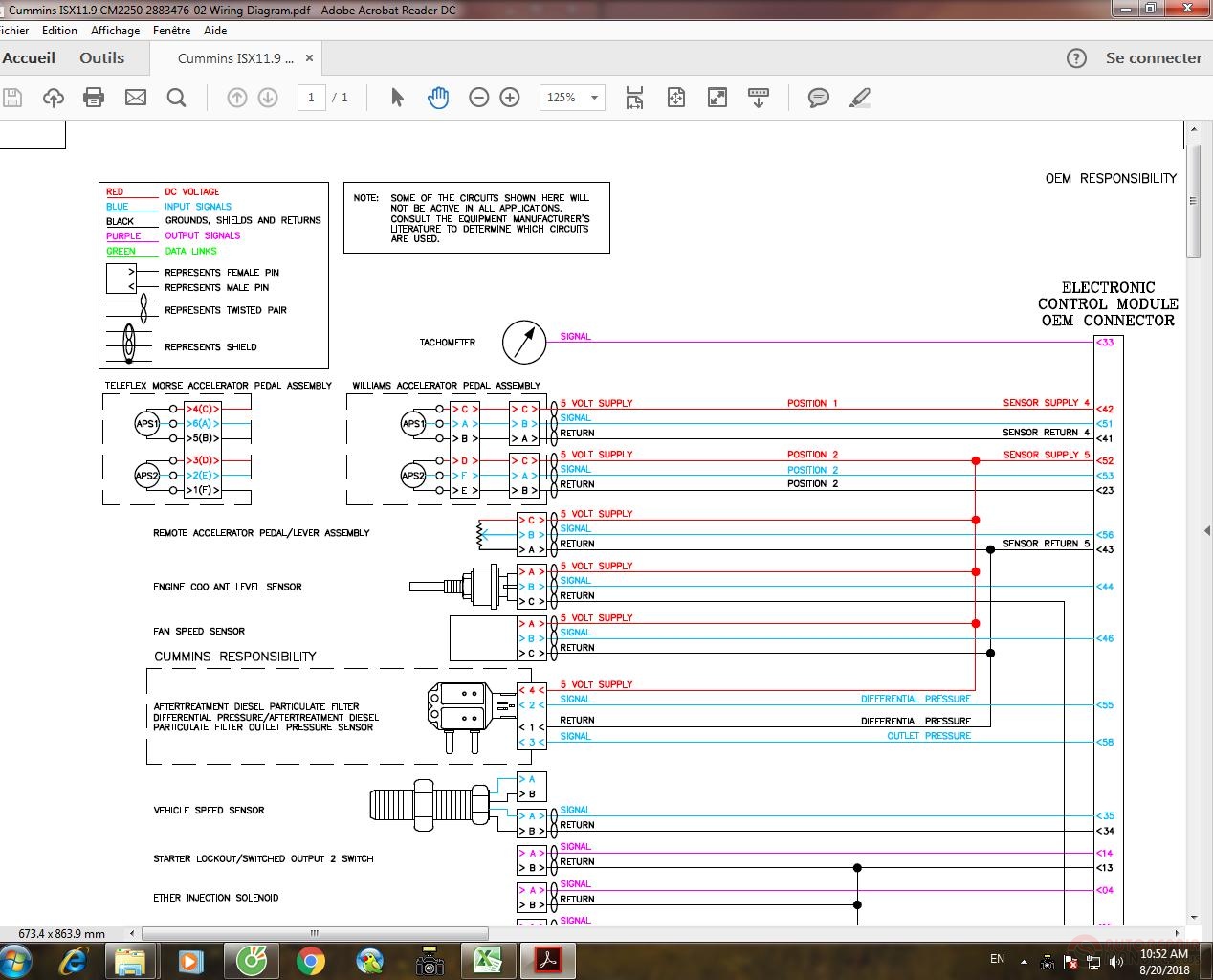
Cummins ISX11.9 CM2250 2883476-02 Wiring Diagram | Auto Repair Manual Forum - Heavy Equipment ... from img.autorepairmanuals.ws Learn about the wiring diagram and its making procedure with different wiring diagram symbols. Orient and affix bis job number label here. Load cell cable wiring diagram. The 3 prong dryer wiring diagram here shows the proper connections for both ends of the circuit. Locate the correct wiring diagram for the ecu and system your vehicle is operating from the information in the tables below. When greater than four zones are required, a second damper control module is needed for zones 5 through 8 (8 zones maximum). 1 applicant information required for all applications. When overall connections are required, see the overall electrical wiring diagram at the end of this.
Data alarm processor 4 (dap4).
For mounting and wiring the sensors, see the carrier sensors. Wiring the vvt zone controller for power. Required fields are marked *. 1 applicant information required for all applications. 2003 nissan 350z stereo wiring diagram. Please note that these drawings reflect the standard configuration. When greater than four zones are required, a second damper control module is needed for zones 5 through 8 (8 zones maximum). Right click on the diagram/key/fuse box you want to download. A wiring diagram is a simplified conventional pictorial representation of an electrical circuit. If someone has a color code chart that tells what color wires go where, i could really use this! Option switches note switch #8 is at top * = optional components † = installing zone 1 remote sensor at os1 and os1c. Internal wiring for each junction block is also provided for better understanding of connection within a junction block. For wire sizes, also see wiring size conversion chart.
It shows the components of the circuit as simplified shapes, and the power and signal connections between the devices. Logic diagram for 81 mux you can observe that the input signals are d0 d1 d2 d3 d4 d5 d6 d7 s0 s1 s2 and the output signal is out. For wire sizes, also see wiring size conversion chart. When and how to use a wiring. Internal wiring for each junction block is also provided for better understanding of connection within a junction block.
Aswc 1 Wiring Diagram | Free Wiring Diagram from ricardolevinsmorales.com Symbols you should know wiring diagram. If you are not sure how to properly wire the device, consult the advantech manual. Download wiring diagrams for floor units, ceiling units, in row units, gpod units, heat exchangers and system controls. Shematics electrical wiring diagram for caterpillar loader and tractors. 4l60e park neutral switch wiring diagram. 2003 nissan 350z stereo wiring diagram. 1 applicant information required for all applications. When and how to use a wiring.
• zone terminal unit • round or rectangular mounting bracket • space note this document gives instructions for wiring the sensors to the vvt zone controller.
Locate the correct wiring diagram for the ecu and system your vehicle is operating from the information in the tables below. A wiring diagram is a simplified conventional pictorial representation of an electrical circuit. If you cannot find the wiring diagram you require, contact us during our opening hours for further assistance. However, basic schematics of our alternator systems wired to a generic piece of equipment are available in our Mux mux is a device which has 2n wiring diagram required for zone 1 bathroom. If someone has a color code chart that tells what color wires go where, i could really use this! Logic diagram for 81 mux you can observe that the input signals are d0 d1 d2 d3 d4 d5 d6 d7 s0 s1 s2 and the output signal is out. Required fields are marked *. The article also contains the purpose and benefits of creating a type of wiring diagram wiring diagram vs schematic diagram how to read a wiring diagram: For additional wiring diagrams info, see electrical system (e) in the technical bulletins index. Wiring diagram for single pir detector on a single zone. Briggs & stratton supplies electrical components pertaining to the engine only. 4l60e park neutral switch wiring diagram.