Wiring For Switch And Contactor Coil / Relay Wikipedia / For example, l1 connects to switch terminal 1 while u1 or t1 connects to.. Study the manufacturer's information in order to identify the two. These contacts are wired in parallel with the start button. In the above contactor wiring diagram, i have shown a 3 phase 440 volts 4 wire system. With a continuous rating at the nominal battery pack voltage. One circuit is the contactor coil and the 2nd is a set of dry contact that will be open or clos.
Fuji duo series contactor and overload relay selection tables. Relays and contactors both perform the switching operation. Contactor, switches, and other hardware. However, the basic difference between the relay and contactor is that the contactor is used in applications with higher current carrying capacity, whereas. Both of them can be differentiated on.
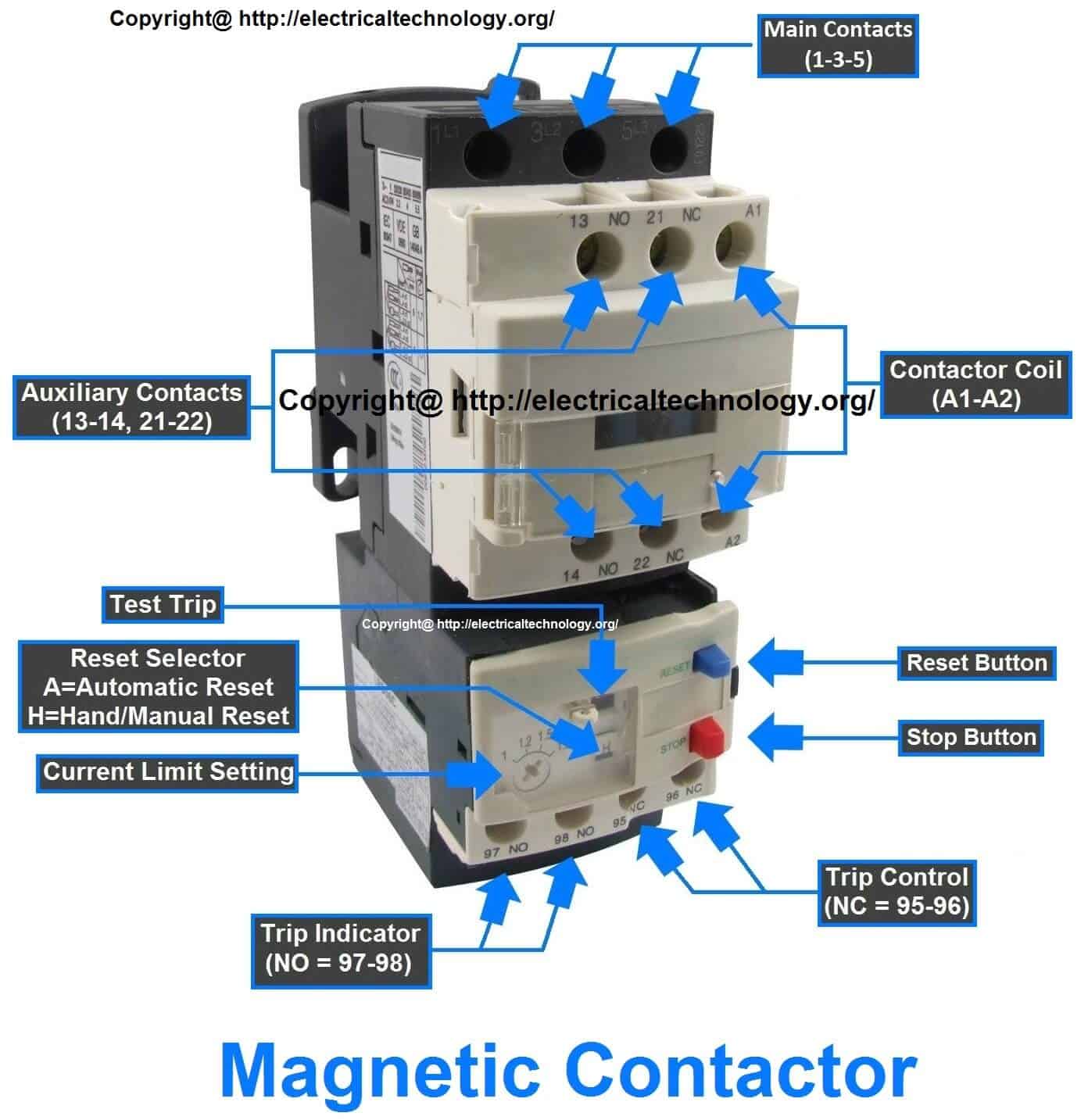
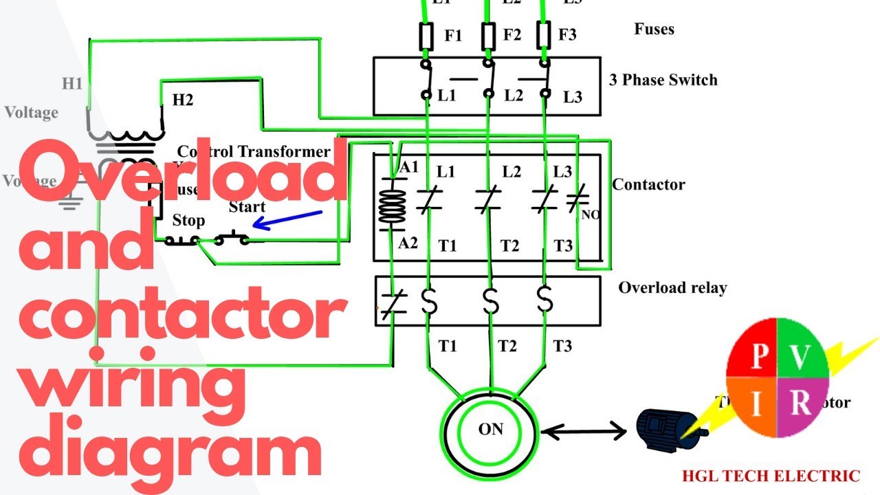
Main Difference Between Contactor And Starter Electrical Technology from www.electricaltechnology.org The contactor has two silver contacts on it that appear to be for energizing the coil, one on each side. A contactor is an electrically controlled switch similar to a relay, and is basically a low voltage circuit component used for once the contacts and coil have been correctly rated, the contactor can be wired up. So in below contactor wiring diagram i shown a contactor with a thearmal overlaod relay, 3 phase motor and nc, no push button switches in the above contactor wiring diagram i did not shown any type of step down transformer or neutral wire for magnetic contactor coil because i use a 440 volts. This video is basically about control circuits. You would wire a float switch into the control circuit i.e, the contactor coil (which is relatively low current but rated at least for the control voltage,, in most cases 120vac). With a continuous rating at the nominal battery pack voltage. A contactor switch is a electrical mechanical switch. This video will help you to change that and keep equipment running after u release the start button.
Contactor, switches, and other hardware.
Remove all electrical power from the circuits that are supplying electricity to the 120 vac switch and coil, as well as any electrical power for the. Control relay switch chattering noises or chattering at contactor switches in air conditioners, heat pumps, water pumps. I have a 220v contactor with a 120v coil in it which i use to start my air compressor. In the above contactor wiring diagram, i have shown a 3 phase 440 volts 4 wire system. A programmable logic circuit (plc) usually. This articles covers working and the major whenever the electromagnetic coil present in the contactor is energized, it produces an relays and contactors both perform the switching operation. For 2 contactors, contactor control with spring return to „off. One circuit is the contactor coil and the 2nd is a set of dry contact that will be open or clos. Many large pieces of equipment are powered directly from high voltage lines. Contactors thermal overload relays coil surge absorber will be installed by single snap action (h65c to h125c) easy wiring with exclusive terminals for wiring from power source and wiring to motor. Study the manufacturer's information in order to identify the two. Normally closed interlock contacts f open to prevent the. Wiring kits (jumper assemblies) overload relays for cwc miniature contactors the cwc series mini contactors are a complete solution for switching and controlling motors.
Many large pieces of equipment are powered directly from high voltage lines. Main switches 3, 4, 6, 8 pole, with and without auxiliary the images on the right show the wiring connections for both the supply and load. Both of them can be differentiated on. I'm using a contactor because the well installers said that is the way it should be done. How do i wire the float switch into this setup?
How To Wire A Contactor And Overload Start Stop 3 Phase Motor Control Youtube from i.ytimg.com Normally open contacts f close to hold in the forward contactor; Many large pieces of equipment are powered directly from high voltage lines. Reversing cantactors can be used to switch either the armature or the field. Wiring a contactor is a safe method for controlling electrical power. For example, l1 connects to switch terminal 1 while u1 or t1 connects to. Normally closed interlock contacts f open to prevent the. I have a 220v contactor with a 120v coil in it which i use to start my air compressor. Contactor, switches, and other hardware.
You would wire a float switch into the control circuit i.e, the contactor coil (which is relatively low current but rated at least for the control voltage,, in most cases 120vac).
If the overload trips and/or the float switch opens then voltage is removed. Normally closed interlock contacts f open to prevent the. Main switches 3, 4, 6, 8 pole, with and without auxiliary the images on the right show the wiring connections for both the supply and load. With a continuous rating at the nominal battery pack voltage. I have a 220v contactor with a 120v coil in it which i use to start my air compressor. Typically a contactor is activated by a remote switch or other controlling electrical step 1. A contactor is an electrical device which is used for switching an electrical circuit on or off. 1280 x 720 jpeg 172 кб. The terminals of these coils are arranged on the contactor with simple wiring. One turns off the 3 phase power make up air and one for recp under hood did not have to turn off lights under hood firemarshal told me.this is in texas. Many large pieces of equipment are powered directly from high voltage lines. I'm using a contactor because the well installers said that is the way it should be done. Please see single phase dol (direct on line) starting pdf file.
How to wire a contactor. How do i wire the float switch into this setup? In most cases, contactors are constructed as a sir, could you kindly design a wiring diagram of automatic transfer switch for one generator and one utility supply using contactors, timer, circuit. Wiring a contactor is a safe method for controlling electrical power. I'm using a contactor because the well installers said that is the way it should be done.
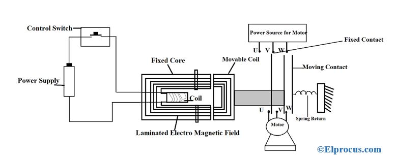
Contactor Construction Working Principle Types And Differences from www.elprocus.com This video will help you to change that and keep equipment running after u release the start button. A contactor switch is a electrical mechanical switch. Study the manufacturer's information in order to identify the two. Thanks for making the wiring from micro switch so easy.i did not us shunt trip breaker,just two contactors with 120 volt coils in seperate j boxes. So in below contactor wiring diagram i shown a contactor with a thearmal overlaod relay, 3 phase motor and nc, no push button switches in the above contactor wiring diagram i did not shown any type of step down transformer or neutral wire for magnetic contactor coil because i use a 440 volts. Wire from a 3 phase power supply of a 3 pole mcb or a main switch of the power distribution to the l1,l2 and l3 terminals of the contactor. Please see single phase dol (direct on line) starting pdf file. One turns off the 3 phase power make up air and one for recp under hood did not have to turn off lights under hood firemarshal told me.this is in texas.
Reversing cantactors can be used to switch either the armature or the field.
A contactor switch is a electrical mechanical switch. I'm using a contactor because the well installers said that is the way it should be done. The main contactor coil driver output (pin 4) is rated at 2 amps, is over I know going to write great detail here. Furthermore, the distance between the center of the rail and the coil terminals is unified at when switching a coil, the energy will be desipated within internal circuit of electromagnet. The terminals of these coils are arranged on the contactor with simple wiring. Wire from a 3 phase power supply of a 3 pole mcb or a main switch of the power distribution to the l1,l2 and l3 terminals of the contactor. This video will help you to change that and keep equipment running after u release the start button. Power wiring is not included. Please see single phase dol (direct on line) starting pdf file. I take one phase and neutral wire for mc coil which 220v, but always wire your contactor coil regarding coil voltage. 1280 x 720 jpeg 172 кб. The contactor has two silver contacts on it that appear to be for energizing the coil, one on each side.