Home
› Solar Panel Charge Controller Wiring Diagram - 12v Solar Charge Controller Circuit : A 2 kw, 4 kw, and 8 kw system are shown and include the solar panels, combiner boxes, charge controller(s), power inverter(s), battery bank, shunt & meter circuits, ac breaker panel, and ac generator wiring.
Solar Panel Charge Controller Wiring Diagram - 12v Solar Charge Controller Circuit : A 2 kw, 4 kw, and 8 kw system are shown and include the solar panels, combiner boxes, charge controller(s), power inverter(s), battery bank, shunt & meter circuits, ac breaker panel, and ac generator wiring.
Solar Panel Charge Controller Wiring Diagram - 12v Solar Charge Controller Circuit : A 2 kw, 4 kw, and 8 kw system are shown and include the solar panels, combiner boxes, charge controller(s), power inverter(s), battery bank, shunt & meter circuits, ac breaker panel, and ac generator wiring.. Wiring is the same for each kit. Pwm solar charge controller installation. Battery and inverter are connected to the battery terminals (positive & negative) of the charge controller. This also aligns with the maximum capacity of the charge controller selected. I'm using an old set of truck jumper wires that are #1 or #2 awg.
Wire the battery to the charge controller and then the solar panel to the charge controller ensuring the correct polarity is observed (see. Second, then connect your solar panel to your charge. Connect the two solar panels to the charge controller. Solar system wiring diagram best solar panel charge controller. Battery and inverter are connected to the battery terminals (positive & negative) of the charge controller.
Off Grid Solar Setup Solar Wiring Diagram With Inverter And Charge Controller Youtube from i.ytimg.com Charge controller to battery fuse/breaker Second, then connect your solar panel to your charge. Connect the two solar panels to the charge controller. Charge controller wiring diagram for diy wind turbine or solar panels. Proper rccb connection diagram with mcb. Wire the battery to the charge controller and then the solar panel to the charge controller ensuring the correct polarity is observed (see. So we will continue the example with the series connection. How to connect a battery bank 12 volt system to solar and charge controller/inverter.
Charge controller wiring diagram for diy wind turbine or solar panels.
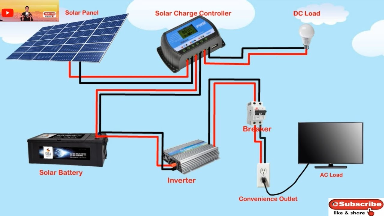
In the diagram the auto 12 volts, 24 volts, 48 volts pwm (pulse width modulation controller) solar charge controller wiring shown. Connect pv panel module to mppt charge controller. This diagram shows the basic setup for those who wish to build their own wind or solar energy project. The complete installation diagram with main supply, solar panels, inverter/ups and load connection. Solar panels to unit to battery and do i need to put a fuse or circuit breaker somewhere what size if i do any help would be great thanks i have 1 300w solar panel and two 12v batteries. Second, then connect your solar panel to your charge. Wire the battery to the charge controller and then the solar panel to the charge controller ensuring the correct polarity is observed (see. The connections for the remote brake are also below. Combination charge controller & divert load. Solar panel cables (or solar wires)are rated to handle the current from the panels, connecting them to the charge controller. Each panel is equipped with a zamp solar plug and simply plugs into the solar roof cap. Magnificent solar panel setup diagram sketch best for. Charge controller wiring diagram for diy wind turbine or solar panels.
Most of the time, you are going to use the series connection. Connecting the solar panel charge controller (mppt or pwm are the same), solar battery and the pv array in the right way is the essential work before enjoying the solar energy. As you see in the connection diagram at first, the solar panel is connected to the solar charge controller and then a 24v battery is connected to the charge controller. The following solar panel wiring diagram shows that an 120w, 12v solar panel is directly connected to the 12v charge controller. So we will continue the example with the series connection.
Build A 12v Solar Charger System For Camping A Caravan Or A Shed Gloopa Co Uk from gloopa.co.uk Each panel is equipped with a zamp solar plug and simply plugs into the solar roof cap. This also aligns with the maximum capacity of the charge controller selected. The wire from the solar panel will be too short to run to your charge controller. The connections for the remote brake are also below. More infomation can be found at ecoelementals.co.uk. This diagram also shows how to wire multiple solar arrays through multiple charge controllers into the lynx distributor. The complete installation diagram with main supply, solar panels, inverter/ups and load connection. Charge controller to battery fuse/breaker
Wiring is the same for each kit.
This diagram also features full system monitoring through the victron gx line of devices. Proper rccb connection diagram with mcb. The connections for the remote brake are also below. These example system diagrams will show how to connect the components of a solar energy system. In order to wire the solar charge controller to the battery i need to make custom wires. We will directly connect them to the charge controller, battery and dc loads. Connect the two solar panels to the charge controller. The complete installation diagram with main supply, solar panels, inverter/ups and load connection. Wiring diagram for our 30a deluxe hardwired solar kits each of our deluxe kits come with a 30 amp digital deluxe solar charge controller and a zamp solar 3 port solar roof cap. Determine the mounting location of the solar panel(s). Connecting the solar panel charge controller (mppt or pwm are the same), solar battery and the pv array in the right way is the essential work before enjoying the solar energy. In the diagram the auto 12 volts, 24 volts, 48 volts pwm (pulse width modulation controller) solar charge controller wiring shown. Pwm solar charge controller installation.
F grid solar system wiring diagram lovely great 220v wiring basics. I power my workshop with solar. Magnificent solar panel setup diagram sketch best for. Connecting the solar panel charge controller (mppt or pwm are the same), solar battery and the pv array in the right way is the essential work before enjoying the solar energy. Components of the charge controller 3.1.
Amazon Com 20a Solar Charge Controller Solar Panel Battery Intelligent Regulator With Dual Usb Port 12v 24v Pwm Auto Paremeter Adjustable Lcd Display Garden Outdoor from images-na.ssl-images-amazon.com This diagram shows the basic setup for those who wish to build their own wind or solar energy project. Magnificent solar panel setup diagram sketch best for. Most of the time, you are going to use the series connection. Battery and inverter are connected to the battery terminals (positive & negative) of the charge controller. We understand what you ask, know deeply what you want, and provide exactly what you need. I power my workshop with solar. Charge controller to battery fuse/breaker I brought the 100/30 mppt charge controller wanting a full wiring diagram picture how to wire it up as i'm not sure.
I'm using an old set of truck jumper wires that are #1 or #2 awg.
Dc load is also connected to the dc output terminal of the charge controller. Windynation 100w solar kit (pwm charge controller and battery included) *fuses and wire gage size are going to vary depend on how long your are running the wires. As you see in the connection diagram at first, the solar panel is connected to the solar charge controller and then a 24v battery is connected to the charge controller. First connect the +ve from the solar panel to the centre pole of the relay then connect a red wire from battery to n.o of the relay. How to connect a battery bank 12 volt system to solar and charge controller/inverter. This diagram also shows how to wire multiple solar arrays through multiple charge controllers into the lynx distributor. The fig show the wiring diagram of the ssc. In order to wire the solar charge controller to the battery i need to make custom wires. Use this wire to extend it so it can reach your charge controller. F grid solar system wiring diagram lovely great 220v wiring basics. I power my workshop with solar. The following solar panel wiring diagram shows that a 12v, 120w pv panel is connected to the solar charge controller (panel negative terminal of panel to the negative terminal of mppt charge controller and vice versa for positive terminal. Solar panel cables (or solar wires)are rated to handle the current from the panels, connecting them to the charge controller.