Home
› 240V Pid Controller Wiring Diagram - Ht Oven Build Question Bladeforums Com : Cn1501 series controller offers 5 ramp and soak programs with 10 segments each with thermocouple, thermistor and process input models with pid control and optional alarms.
240V Pid Controller Wiring Diagram - Ht Oven Build Question Bladeforums Com : Cn1501 series controller offers 5 ramp and soak programs with 10 segments each with thermocouple, thermistor and process input models with pid control and optional alarms.
240V Pid Controller Wiring Diagram - Ht Oven Build Question Bladeforums Com : Cn1501 series controller offers 5 ramp and soak programs with 10 segments each with thermocouple, thermistor and process input models with pid control and optional alarms.. There are two types of systems; Proportional is the actual variance in temperature. As you see in block diagram of pid controller, the error essentially goes through each pid block and their outputs are summed up and form a control signal that drives the process to the desired setpoint. 2) for pid500 refer input jumper selection as in point no. This post is bout arduino and pid based dc motor position control, arduino control pid is the part of programming, on which a complex calculation carried out by controller and manipulate the output do the wiring as shown in the image above, encoder green and white wire must be connected to the.
When a temperature change occurs, a millivolt voltage is created. Implementing pid controller using arduino. 2) for pid500 refer input jumper selection as in point no. Pid temperature controller wiring diagram schemati. Before explaining pid controller, let's revise about control system.
Wiring An Itc100 Vl The Homebrew Forum from www.thehomebrewforum.co.uk A wiring diagram is a simplified standard photographic representation of an electric circuit. It reveals the components of the circuit as streamlined shapes, and the power and also signal connections in between the devices. This channel is designed to offer insight and background on the science, art and practice of making alcohol based products at home.parts listitc 106 vh. Cn1501 series controller offers 5 ramp and soak programs with 10 segments each with thermocouple, thermistor and process input models with pid control and optional alarms. Almost on all available projects, originators would like to control motor speeds and direction together, but they prefer mainly directly sending pwm to dc motors, even via a motor control circuit. A pid system uses proportional, integral, and derivative drive elements to control a process. Thermocouples use two wires made of different metals that are welded together at the sensing end. This channel is designed to offer insight and background on the science, art and practice of making alcohol based products at home.major parts list:pid.
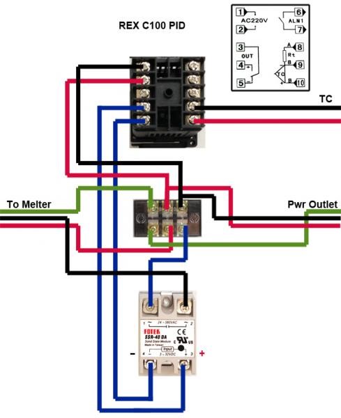
3) for 2 wire rtd short terminals 8 & 9 (for pid500) and terminals 3 & 4.
Control of speed and direction of dc motors by pid controller and pwm outputs. There are two types of systems; This channel is designed to offer insight and background on the science, art and practice of making alcohol based products at home. This channel is designed to offer insight and background on the science, art and practice of making alcohol based products at home.parts listitc 106 vh. The pid controller — part 1 | nuts & volts magazine the term pid is an acronym that stands for proportional integral derivative. When a temperature change occurs, a millivolt voltage is created. Click the register link above to proceed. This channel is designed to offer insight and background on the science, art and practice of making alcohol based products at home.major parts list:pid. A wiring diagram is a simplified standard photographic representation of an electric circuit. Almost on all available projects, originators would like to control motor speeds and direction together, but they prefer mainly directly sending pwm to dc motors, even via a motor control circuit. Cn1501 series controller offers 5 ramp and soak programs with 10 segments each with thermocouple, thermistor and process input models with pid control and optional alarms. A pid controller is part of a feedback system. 2) for pid500 refer input jumper selection as in point no.
When a temperature change occurs, a millivolt voltage is created. Cn1501 series controller offers 5 ramp and soak programs with 10 segments each with thermocouple, thermistor and process input models with pid control and optional alarms. A close loop system is also known as feedback control system and this type of system is used to design automatically stable system at desired output or. A pid controller is part of a feedback system. There are two types of systems;
Pid Theromocoupler Control from forum.castbulletassoc.org Collection of pid temperature controller wiring diagram. Click the register link above to proceed. A pid system uses proportional, integral, and derivative drive elements to control a process. Pid stands for proportional, integral, derivative. I am in uk, voltage is 240v in house, i guess as the power went off on both attempts (in garage socket and house. It reveals the components of the circuit as streamlined shapes, and the power and also signal connections in between the devices. Pid temperature controller wiring diagram schemati. Almost on all available projects, originators would like to control motor speeds and direction together, but they prefer mainly directly sending pwm to dc motors, even via a motor control circuit.
Digital indicating controller (power supply:
A close loop system is also known as feedback control system and this type of system is used to design automatically stable system at desired output or. There are two types of systems; Cn1501 series controller offers 5 ramp and soak programs with 10 segments each with thermocouple, thermistor and process input models with pid control and optional alarms. A pid controller is part of a feedback system. Before explaining pid controller, let's revise about control system. I am in uk, voltage is 240v in house, i guess as the power went off on both attempts (in garage socket and house. Pid stands for proportional, integral, derivative. Controlling pressures, levels, or flowrates. Advanced, full featured pid temperature controller. The pid controller — part 1 | nuts & volts magazine the term pid is an acronym that stands for proportional integral derivative. It reveals the components of the circuit as streamlined shapes, and the power and also signal connections in between the devices. This channel is designed to offer insight and background on the science, art and practice of making alcohol based products at home. Implementing pid controller using arduino.
Thermocouples use two wires made of different metals that are welded together at the sensing end. As you see in block diagram of pid controller, the error essentially goes through each pid block and their outputs are summed up and form a control signal that drives the process to the desired setpoint. 2) for pid500 refer input jumper selection as in point no. Collection of pid temperature controller wiring diagram. Open loop system and close loop system.
Electronic Brewery Wiring Diagram Full Hd Version Wiring Diagram Loth Diagram Discoclassic It from www.nchomebrewing.com Pid stands for proportional, integral, derivative. What is a pid controller? Implementing pid controller using arduino. Control of speed and direction of dc motors by pid controller and pwm outputs. Digital indicating controller (power supply: Almost on all available projects, originators would like to control motor speeds and direction together, but they prefer mainly directly sending pwm to dc motors, even via a motor control circuit. A pid system uses proportional, integral, and derivative drive elements to control a process. Click the register link above to proceed.
A pid system uses proportional, integral, and derivative drive elements to control a process.
This channel is designed to offer insight and background on the science, art and practice of making alcohol based products at home. 2) for pid500 refer input jumper selection as in point no. This post is bout arduino and pid based dc motor position control, arduino control pid is the part of programming, on which a complex calculation carried out by controller and manipulate the output do the wiring as shown in the image above, encoder green and white wire must be connected to the. Advanced, full featured pid temperature controller. There are two types of systems; Temperature wire and cable tools. Pid temperature controller wiring diagram schemati. Controlling pressures, levels, or flowrates. When a temperature change occurs, a millivolt voltage is created. Collection of pid temperature controller wiring diagram. Digital indicating controller (power supply: Cn1501 series controller offers 5 ramp and soak programs with 10 segments each with thermocouple, thermistor and process input models with pid control and optional alarms. 3) for 2 wire rtd short terminals 8 & 9 (for pid500) and terminals 3 & 4.