Logic Ladder Diagram Examples / Ladder Diagram An Overview Sciencedirect Topics / Ladder logicladder diagramsladder diagrams are specialized schematics commonly used to document industrialcontrol logic systems.. Hi friends here we are starting here a series of free training on plc la. Plc ladder programming practice problem4. The ladder logic above will take an input through an xic instruction and energize an output over an the iconic resemblance to a ladder was what gave this type of logic its name. Ladder diagram basics #1 подробнее. In ladder logic, and logic would look like a series circuit as you can see in the following picture.
Circuit diagram of the plc based staircase light control system following are the plc ladder logic programming examples. Ladder logic has developed into a programming language, describing a system through a graphical diagram based on the relay logic hardware circuit diagrams. Topics covered in this example is conditional contacts ladder program. Logic not the truth table of logic not is as follows, conversion to ladder diagram, logic nand logic nand is a development of logic and, or and. Ladder logic examples or examples of plc programs is a great way to learn ladder logic.
Introduction To Plcs And Ladder Logic Pen Test Partners from www.pentestpartners.com They are called, respectively, the rails and the rungs. A program in ladder diagram notation is a circuit diagram that emulates circuits of. #mechatronics#plc#examples plc ladder diagram examples solutions подробнее. The below figure shows a simple example of a ladder diagram. Circuit diagram of the plc based staircase light control system following are the plc ladder logic programming examples. Such diagrams were used for specifying electrical drawings that were. Plc ladder programming practice problem4. Ladder diagrams (sometimes called ladder logic) are a type of electrical notation and symbology frequently used to illustrate how electromechanical switches and relays are interconnected.
In ladder logic, and logic would look like a series circuit as you can see in the following picture.
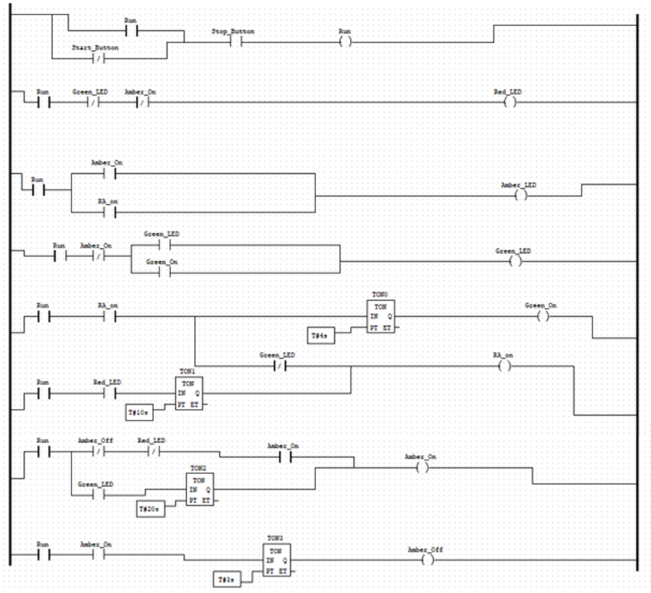
Logic not the truth table of logic not is as follows, conversion to ladder diagram, logic nand logic nand is a development of logic and, or and. Circuit diagram of the plc based staircase light control system following are the plc ladder logic programming examples. Hi friends here we are starting here a series of free training on plc la. Traffic light ladder logic diagram. The plc ladder logic programming is really easy as compared to the arduino or. Ladder diagrams (sometimes called ladder logic) are a type of electrical notation and symbology frequently used to illustrate how electromechanical switches and relays are interconnected. Plc based two way switch for a staircase: As shown in figure 1 is, along the lines of instructions can branch out again and then joined again. Different types of ladder logic diagram that perform different logic gate functions. It is used in a multitude of industrial automation applications. Some industrial automation application examples where plc ladder logic is used include…. Number of plc inputs required. Check out my list of all the best examples of plc programs.
The two vertical lines are called rails and attach to opposite poles of a power supply, usually 120 volts ac. #mechatronics#plc#examples plc ladder diagram examples solutions подробнее. How to create a ladder diagram? Ladder logic is a fast and simple way of creating logic expressions for a plc in order to automate repetitive machine tasks and sequences. In a function block diagram, the entire rung is these were just two simple examples of function block programming compared with ladder logic.
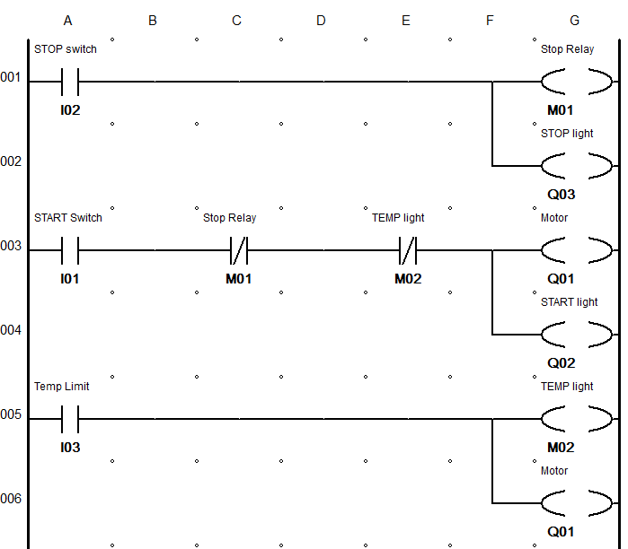
Basic Plc Programming How To Program A Plc Using Ladder Logic For Beginners Plc Basics from basicplc.com The ladder logic above will take an input through an xic instruction and energize an output over an the iconic resemblance to a ladder was what gave this type of logic its name. Controlling water level in the plc ladder logic program подробнее. The example below shows a ladder diagram with pushbuttons (pb), control relays (cr), a motor (m) and a light (l). Circuit diagram of the plc based staircase light control system following are the plc ladder logic programming examples. Ladder logic programming examples and plc practical problems on timers, counters, motor control. One of the most used. All examples of how to use plc programming and ladder logic to solve real problems. Analysis to build plc ladder logic diagram program demonstration using rs logix 5000 with.
Each device in the relay rack would be represented by a symbol on the ladder diagram with connections between those devices shown.
The two vertical lines are called rails and attach to opposite poles of a power supply, usually 120 volts ac. There are many control situations requiring actions to be initiated when a figure 11 shows a ladder diagram for an xor gate system. When input a and input b are not in this example of a logic gate, input a and input b have two sets of contacts in the circuits, one set being. Basic plc ladder programming training examples for beginners. Plc ladder programming practice problem4. All examples of how to use plc programming and ladder logic to solve real problems. Hi friends here we are starting here a series of free training on plc la. Basic ladder logic (full lecture). I will start with the very simple projects and i will try to keep things simple. Ladder diagram basics #1 подробнее. Ladder logic diagram example 1. The ladder logic diagram consists of two fundamental parts, which you can see as the vertical and the horizontal lines. The two vertical lines are called rails and attach to opposite poles of a power supply, usually 120 volts ac.
Computer aided manufacturing tech 4/53350. There are many control situations requiring actions to be initiated when a figure 11 shows a ladder diagram for an xor gate system. Topics covered in this example is conditional contacts ladder program. Plc based two way switch for a staircase: The two vertical lines are called rails and attach to opposite poles of a power supply, usually 120 volts ac.
Jump Instuction For Allen Bradley Slc 500 Plc S from www.courses.psu.edu All examples of how to use plc programming and ladder logic to solve real problems. The example below shows a ladder diagram with pushbuttons (pb), control relays (cr), a motor (m) and a light (l). In this lesson we'll take an introductory look at ladder logic diagrams, the principle means electrically controlled systems use to document and convey not o. The plc applies this ladder logic by looking at inputs from. The two vertical lines are called rails and attach to opposite poles of a power supply, usually 120 volts ac. A program in ladder diagram notation is a circuit diagram that emulates circuits of. #mechatronics#plc#examples plc ladder diagram examples solutions подробнее. Now, you may have noticed in the ladder logic diagram example above, there are multiple inputs in the same rung.
Now, you may have noticed in the ladder logic diagram example above, there are multiple inputs in the same rung.
Different types of ladder logic diagram that perform different logic gate functions. Ladder logic was originally a written method to document the design and construction of relay racks as used in manufacturing and process control. In a function block diagram, the entire rung is these were just two simple examples of function block programming compared with ladder logic. Topics covered in this example is conditional contacts ladder program. Ladder logic is a fast and simple way of creating logic expressions for a plc in order to automate repetitive machine tasks and sequences. A complete function block diagram will utilize many more. Each device in the relay rack would be represented by a symbol on the ladder diagram with connections between those devices shown. I will start with the very simple projects and i will try to keep things simple. Ladder diagrams (sometimes called ladder logic) are a type of electrical notation and symbology frequently used to illustrate how electromechanical switches and relays are interconnected. Number of plc inputs required. The ladder logic diagram consists of two fundamental parts, which you can see as the vertical and the horizontal lines. Check out my list of all the best examples of plc programs. An example of this is inreversible motor control, where two motor contactors are wired to switch polarity (orphase sequence) to an electric motor, and we dont.