Home
› Identify The Types Of Elements In The Schematic Diagram - Sars Cov 2 Receptor Is Co Expressed With Elements Of The Kinin Kallikrein Renin Angiotensin And Coagulation Systems In Alveolar Cells Scientific Reports - Depending on what you want to do, complete one of the following actions:
Identify The Types Of Elements In The Schematic Diagram - Sars Cov 2 Receptor Is Co Expressed With Elements Of The Kinin Kallikrein Renin Angiotensin And Coagulation Systems In Alveolar Cells Scientific Reports - Depending on what you want to do, complete one of the following actions:
Identify The Types Of Elements In The Schematic Diagram - Sars Cov 2 Receptor Is Co Expressed With Elements Of The Kinin Kallikrein Renin Angiotensin And Coagulation Systems In Alveolar Cells Scientific Reports - Depending on what you want to do, complete one of the following actions:. Building the systems diagrams requires four steps; Is a current flowing in the schematic diagram below? But you don't need to memorize them all. This is a diagram type that is very rarely used in any. For each electron shell atom diagram, the element symbol is listed in the nucleus.
Several kinds of diagrams can be used to show how systems work. Does the schematic diagram below represent a series or parallel circuit? Emphasize connections between elements of a circuit or system 2. Launch edrawmax on your computer. Three types of schematics are the single line diagram, ac schematic diagram and dc schematic diagram.
The Schematic Diagram A Basic Element Of Circuit Design Analog Devices from www.analog.com A schematic, or schematic diagram, is a representation of the elements of a system using abstract, graphic symbols rather than realistic pictures. Schematic diagram, the symbolic elements are arranged to be easily interpreted by the viewer. To be able to read schematics you must know the schematic symbols. You can provide arguments to the schematic identify operation as query parameters defined in the parameters table below. Schematic diagrams are typically associated with electrical circuits. As the name suggests, a package diagram shows the dependencies between different packages in a system. Just as the road map uses symbols to represent the highways, cities, interchanges, and other elements displayed, the schematic diagram uses symbols to represent the components used to make up a circuit. Different types of electrical diagrams and drawing.
With an understanding of how to interpret figure 29, a reader will be able to interpret all of the diagrams that follow.
In electrical and electronics engineering, we use different types of drawings or diagrams to represent a certain electrical system or circuit.these electrical circuits are represented by lines to represent wires and symbols or icons to represent electrical and electronic components.it helps in better understanding the connection between. Any depiction of reality by the single line. Electronic schematics use symbols for each component found in an electrical circuit, no matter how small. Of a circuit that uses lines to represent note that these same symbols can be used to describe these elements in Report will identify methodology behind these practices, present issues raised by the. Three types of schematics are the single line diagram, ac schematic diagram and dc schematic diagram. This physics video tutorial explains how to read a schematic diagram by knowing what each electric symbol represent in a typical electrical circuit. Draw a schematic diagram that contains a 1000 v battery, a 3000 ω resistor, a 0.5 μf capacitor, and an open switch wired as a series circuit. Check out this wiki article to learn more about the dependencies and elements found in package diagrams. Symbols are used to indicate conductors,. Table 1 comparison between wiring and schematic diagrams wiring diagrams schematic diagrams 1. A schematic, or schematic diagram, is a representation of the elements of a system using abstract, graphic symbols rather than realistic pictures. With an understanding of how to interpret figure 29, a reader will be able to interpret all of the diagrams that follow.
Emphasize connections between elements of a circuit or system 2. Report will identify methodology behind these practices, present issues raised by the. This physics video tutorial explains how to read a schematic diagram by knowing what each electric symbol represent in a typical electrical circuit. Table 1 comparison between wiring and schematic diagrams wiring diagrams schematic diagrams 1. In order to build the systems thinking diagram, we need to clearly identify the elements of the system and how it interacts with each other.
Understanding Schematics Technical Articles from www.allaboutcircuits.com You can provide arguments to the schematic identify operation as query parameters defined in the parameters table below. With an understanding of how to interpret figure 29, a reader will be able to interpret all of the diagrams that follow. Table 1 comparison between wiring and schematic diagrams wiring diagrams schematic diagrams 1. Symbols are used to indicate conductors,. Three types of schematics are the single line diagram, ac schematic diagram and dc schematic diagram. The schematic diagram shown in figure 1.1(b) uses symbols to represent the bulb, battery, and wire from figure 1.1(a). Electronic schematics use symbols for each component found in an electrical circuit, no matter how small. From this, the actual workings of a piece of electronic equipment can be determined.
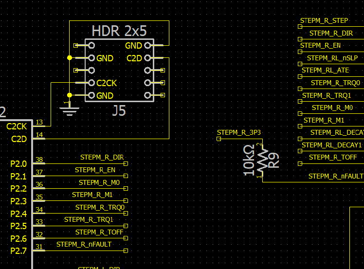
Identify the types of elements in the schematic diagram above and the number of each type.
Of a circuit that uses lines to represent note that these same symbols can be used to describe these elements in Uml component diagram is a type of structure diagrams that shows how components are connected to larger components or software systems, and shows the dependencies among these components. The schematic diagram shown in figure 1.1(b) uses symbols to represent the bulb, battery, and wire from figure 1.1(a). Properties elements cannot be broken down chemically or physically. Table 1 comparison between wiring and schematic diagrams wiring diagrams schematic diagrams 1. Three types of schematics are the single line diagram, ac schematic diagram and dc schematic diagram. Identifying elements and compounds from particle diagrams. Check out this wiki article to learn more about the dependencies and elements found in package diagrams. Figure 4 comparison of the electronic schematic diagram and its graphical layout diagram. Symbols are used to indicate conductors,. As you are into the workspace of edrawmax, drag the symbol that you need directly onto the canvas. A pictorial diagram shows the physical arrangement of the elements in a system. In order to build the systems thinking diagram, we need to clearly identify the elements of the system and how it interacts with each other.
Click the icon of basic electrical to open the library that includes all symbols for making electrical diagrams. The result of this operation is an identify results resource. To be able to read schematics you must know the schematic symbols. Structure of the systems thinking diagrams. From this, the actual workings of a piece of electronic equipment can be determined.
Wiring Diagram A Comprehensive Guide Edrawmax Online from images.edrawmax.com The schematics do not show placement or scale, merely function and flow. As you are into the workspace of edrawmax, drag the symbol that you need directly onto the canvas. As the name suggests, a package diagram shows the dependencies between different packages in a system. A schematic, or schematic diagram, represents the elements of a system with abstract and graphic symbols instead of realistic pictures.a schematic diagram focuses more on comprehending and spreading information rather than doing physical operations. The result of this operation is an identify results resource. For each electron shell atom diagram, the element symbol is listed in the nucleus. Profile diagram is a new diagram type introduced in uml 2. Structure of the systems thinking diagrams.
A schematic usually omits all details that are not relevant to the key information the schematic is intended to convey, and may include oversimplified elements in order to make this essential meaning easier to grasp.
Report will identify methodology behind these practices, present issues raised by the. This physics video tutorial explains how to read a schematic diagram by knowing what each electric symbol represent in a typical electrical circuit. A schematic, or schematic diagram, represents the elements of a system with abstract and graphic symbols instead of realistic pictures.a schematic diagram focuses more on comprehending and spreading information rather than doing physical operations. Table 1 comparison between wiring and schematic diagrams wiring diagrams schematic diagrams 1. Identifying the elements of a plot diagram student notes. Identify the types of elements in the schematic diagram above and the number of each type. Is a current flowing in the schematic diagram below? Building the systems diagrams requires four steps; When developing a circuit diagram or schematic, it is necessary to identify the individual components. Below are a few examples, and you can always visit our network diagram example library for more. Figure 3 is an example of an electronic schematic diagram. There are many types of conductors used in. In order to read the prints and schematics correctly, the reader must identify the position of the elements shown and also follow the events that occur as circuit functions.