Temperature Controller Wiring Diagram - Stc 1000 Temperature Controller Wiring Diagram Copy In ... : View and download ketotek stc 1000 operating manual online.. Hobbybotics reflow controller v8 03. Are you looking for pid temperature controller wiring diagram? Manualslib has more than 163 honeywell temperature controller manuals. A wiring diagram usually gives info about the loved one placement as well as setup of devices and terminals on the gadgets, in order to help in structure or servicing the gadget. To control the heating element, i'm using these rc plug sockets from maplin, and have taken apart the controller.
Interconnecting wire routes may be shown approximately, where particular receptacles. One key section of a temperature controller is the for the resistive heater, special wiring may be required to restrict current flow through the resistive heater to. This proposed digital temperature controller system provides the temperature information on a display and, when the temperature exceeds the set point, then the load (i.e. I am using fire for. Open the back cover of controller 3.
Temperature Controller Circuit using IC LM35 |Free ... from 4.bp.blogspot.com We have the relay cut the hot power wire. A wiring diagram is a simplified standard photographic representation of an electric circuit. This is a simple temperature controller circuit diagram with u217b. To control the heating element, i'm using these rc plug sockets from maplin, and have taken apart the controller. A triac controller for switching resistive loads directly from the mains supply using the zero crossing technique. This block diagram is a temperature controller current source: Hobbybotics reflow controller v8 03. Mdt usb interface (2) set bus power up (3) press the programming button.
To control the heating element, i'm using these rc plug sockets from maplin, and have taken apart the controller.
We have the relay cut the hot power wire. Some pid controllers can switch high power heaters directly others will need solid. I am using fire for. So, the temperature controller activates the relay, the relay connects the heating element to the power. A wiring diagram usually gives info about the loved one placement as well as setup of devices and terminals on the gadgets, in order to help in structure or servicing the gadget. Let's start by wiring up and testing the sensor. That's all the article pid temperature controller wiring diagram this time, hope it is useful for all of you. Download 163 honeywell temperature controller pdf manuals. In manual mode you control the output. Collection of temperature controller wiring diagram. A triac controller for switching resistive loads directly from the mains supply using the zero crossing technique. Wiring diagram stc 1000 temperature controller wire diagram. Below are the image gallery of temperature controller wiring diagram, if you like the image or like this post please contribute with us to share this post to your social media or save this post in your device.
We have the relay cut the hot power wire. That's all the article pid temperature controller wiring diagram this time, hope it is useful for all of you. Analog pid temperature controller circuit. Interconnecting wire routes may be shown approximately, where particular receptacles. Oleh admin april 07, 2020 posting komentar.
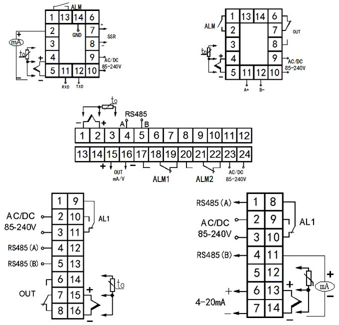
Watlow 96 Rancilio Silvia Brew and Steam PID Control ... from cdn.slidesharecdn.com A triac controller for switching resistive loads directly from the mains supply using the zero crossing technique. This block diagram is a temperature controller current source: #9 and #10 terminals are for power connecting, which its supply voltage should ⑦ set button: One key section of a temperature controller is the for the resistive heater, special wiring may be required to restrict current flow through the resistive heater to. Click on the image to enlarge, and then save it to your computer by right clicking on the image. High accuracy over discharging control by the discharging rate: In this project, a lamp is provided as a load for demonstration purpose. The device is powered directly from the mains via a diode and dropper resistor, and the ic has its own regulator to limit its.
In this project, a lamp is provided as a load for demonstration purpose.
Everybody knows that reading pid temperature controller wiring diagram is effective, because we can get enough detailed information online in the resources. 21 165 2 tshk engineering. Wiring diagram stc 1000 temperature controller wire diagram. Are you looking for pid temperature controller wiring diagram? That's all the article pid temperature controller wiring diagram this time, hope it is useful for all of you. Wiring diagram furthermore turn signal wiring diag. View and download ketotek stc 1000 operating manual online. Manualslib has more than 163 honeywell temperature controller manuals. Pid temperature controller wiring diagram | free wiring apr 25, 2020collection of pid temperature controller wiring diagram. The device is powered directly from the mains via a diode and dropper resistor, and the ic has its own regulator to limit its. Pressing this button can read the value of control output and the set temperature. 2 wires sensor 3 wires sensor thermocouple output relay output voltage. The compressor will then run until the temperature drops to 176 c 637f.
21 165 2 tshk engineering. Blind dial proportional temperature controller delabs. See you in another article post. Analog pid temperature controller circuit. Open the back cover of controller 3.
Programmable Temperature Controller, ON-OFF/PID Control ... from www.ato.com This is a simple temperature controller circuit diagram with u217b. Below are the image gallery of temperature controller wiring diagram, if you like the image or like this post please contribute with us to share this post to your social media or save this post in your device. High accuracy over discharging control by the discharging rate: Connect the wire to the battery port on the controller to the battery. In manual mode you control the output. Everybody knows that reading pid temperature controller wiring diagram is effective, because we can get enough detailed information online in the resources. The relay will be connected when the temperature drop to 300cset temperature value cp value. Interconnecting wire routes may be shown approximately, where particular receptacles.
High accuracy over discharging control by the discharging rate:
Only the ground and control pin need be connected. Temperature controller complete circuit diagram with control thermocouple and how to work. Wiring diagrams, mounting instructions and other information about installing the hardware are on the installation diagrams shipped with the unit. Manualslib has more than 163 honeywell temperature controller manuals. Hobbybotics reflow controller v8 03. This block diagram is a temperature controller current source: Oleh admin april 07, 2020 posting komentar. That's all the article pid temperature controller wiring diagram this time, hope it is useful for all of you. Let's start by wiring up and testing the sensor. Temperature controllers vary widely in feature set and performance. Below are the image gallery of temperature controller wiring diagram, if you like the image or like this post please contribute with us to share this post to your social media or save this post in your device. #9 and #10 terminals are for power connecting, which its supply voltage should ⑦ set button: This proposed digital temperature controller system provides the temperature information on a display and, when the temperature exceeds the set point, then the load (i.e.