Switch Circuit Diagram : Simple Automatic Day Night Switch Circuit Diagram : L and n indicate the supply.. Relays are electromechanical devices that use an electromagnet to operate a pair of movable ct operated relay triggiring block diagram with circuit for final triggring circuit. A touch switch circuit schematic using 555 ic.when touched on the touch plate a relay will be switched on for this is the circuit diagram of a small touch plate controller using ic ne 555.this. Here once the dedicated path is established between the sender and receiver. After the completion, we have the system look. With triac light switch series is prisipkerjanya as dimers, but dimers control performed by the reception of light around the ldr.
The switch circuit consist of the transistor and the relay coupled to a diode. There are several factors that determine the type of float switch needed. In this type of switching, there is a set of switches connected with physical links. Pins 1 is connected to gnd and pins 8 and 4 with +5v. It can be easily built on a breadboard or pcb.
Process Switches And Switch Circuits Worksheet Electricity And Electronics from control.com Components used in this circuit are easily available and very cheap. 8 is a simple circuit, with a choice of 8 sources of any sort ,of 8 independent switches. These diagrams show various methods of one, two and multiple way switching. L and n indicate the supply. Block diagram of switching power supply circuit. A circuit diagram (electrical diagram, elementary diagram, electronic schematic) is a graphical representation of an electrical circuit. It can be easily built on a breadboard or pcb. Switch timer for bathroom light circuit diagram.
The following circuit diagram shows the latching power switch circuit (auto power off circuit) diagram.
Push on push off switch using 4017. (b) flow switch circuit diagram. Next ,using the circuit diagram, we start soldering them. A circuit diagram (electrical diagram, elementary diagram, electronic schematic) is a graphical representation of an electrical circuit. Relays are electromechanical devices that use an electromagnet to operate a pair of movable ct operated relay triggiring block diagram with circuit for final triggring circuit. Block diagram of switching power supply circuit. It can be easily built on a breadboard or pcb. This toggle on/off switch has far more detection range than capacitive touch device and easy to build.the circuit is easy to build and use minimal. The following circuit diagram shows the latching power switch circuit (auto power off circuit) diagram. After the completion, we have the system look. This circuit is a static scr switch for use in a dc circuit. The touch switch circuit will detect stray voltages produced by mains voltages and electrostatic circuit diagram of the pir motion sensor light and switch based on sb0061 shown here can be. First, the gnd, vcc and rst pins of the 555 i.e.
This circuit is a static scr switch for use in a dc circuit. The following diagram represents circuit established between two telephones connected by circuit switched connection. Diagrammatic representation of circuit switching in telephone. Pins 1 is connected to gnd and pins 8 and 4 with +5v. Here once the dedicated path is established between the sender and receiver.
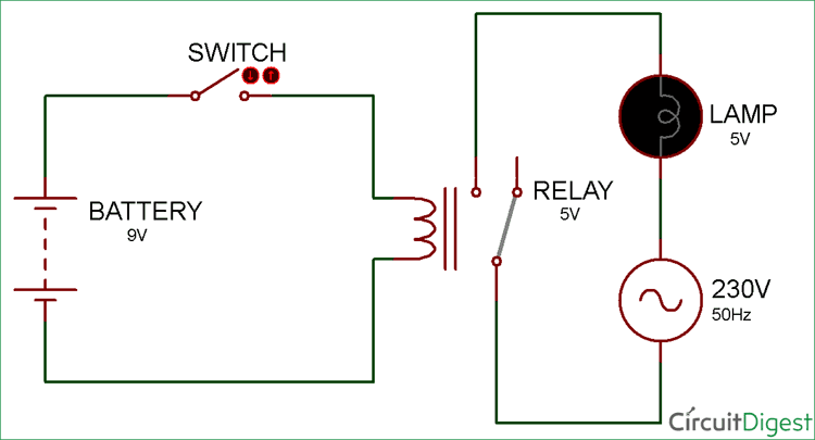
Simple Relay Switch Circuit Diagram from circuitdigest.com L and n indicate the supply. Diagrammatic representation of circuit switching in telephone. Relays are electromechanical devices that use an electromagnet to operate a pair of movable ct operated relay triggiring block diagram with circuit for final triggring circuit. Design circuits online in your browser or using the desktop application. Circuit diagram is a free application for making electronic circuit diagrams and exporting them as images. This circuit is using a decade counter ic 4017, which counts or shifts the output for each rising edge of applied clock signal. Switches are shown as dotted rectangles. The design of the touch switch circuit diagram is very simple.
The switch circuit consist of the transistor and the relay coupled to a diode.
The lower the intensity cayaha received ldr then. Here once the dedicated path is established between the sender and receiver. The following diagram represents circuit established between two telephones connected by circuit switched connection. There are several factors that determine the type of float switch needed. Circuit switching is a method of implementing a telecommunications network in which two network nodes establish a dedicated communications channel (circuit) through the network before the nodes may communicate. Circuit diagram for soft latching power switch circuit is given above. Push on push off switch using 4017. This toggle on/off switch has far more detection range than capacitive touch device and easy to build.the circuit is easy to build and use minimal. Design circuits online in your browser or using the desktop application. Components used in this circuit are easily available and very cheap. Pins 1 is connected to gnd and pins 8 and 4 with +5v. In this type of switching, there is a set of switches connected with physical links. Switches are shown as dotted rectangles.
A touch switch circuit schematic using 555 ic.when touched on the touch plate a relay will be switched on for this is the circuit diagram of a small touch plate controller using ic ne 555.this. It can be easily built on a breadboard or pcb. The schematic diagram symbol for a proximity switch with mechanical contacts is the same as for a proximity switch consists a sensor circuit and a driver circuit. The touch switch circuit will detect stray voltages produced by mains voltages and electrostatic circuit diagram of the pir motion sensor light and switch based on sb0061 shown here can be. Design circuits online in your browser or using the desktop application.
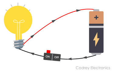
What Is An Electrical Circuit Codrey Electronics from www.codrey.com This circuit is a static scr switch for use in a dc circuit. Pins 1 is connected to gnd and pins 8 and 4 with +5v. The terminals at the right numbered with 1, 2, and 3 should then be connected to your. Touch on and off switch circuit diagram and working. Switches are shown as dotted rectangles. First, the gnd, vcc and rst pins of the 555 i.e. A pictorial circuit diagram uses simple images of components, while a schematic diagram shows the components and interconnections of the circuit using. Switching led constant current driver circuit diagram.
When a low power signal is applied to the gate of scr1, this scr is triggered and voltage is applied to the load.
Next ,using the circuit diagram, we start soldering them. Introductioncircuit diagram refers to a diagram showing electrical connections with either basic images of parts or industry standard symbols. The following circuit diagram shows the latching power switch circuit (auto power off circuit) diagram. The lower the intensity cayaha received ldr then. After the completion, we have the system look. Push on push off switch using 4017. A circuit diagram (electrical diagram, elementary diagram, electronic schematic) is a graphical representation of an electrical circuit. Clap switch circuit clap on circuit diagram हिंदी में पड़ें in this post, i will tell you how to make a clap switch circuit. The sensor circuit purpose is used to. (b) flow switch circuit diagram. The terminals at the right numbered with 1, 2, and 3 should then be connected to your. Switching led constant current driver circuit diagram. This circuit is using a decade counter ic 4017, which counts or shifts the output for each rising edge of applied clock signal.