Home
› On Off Switch Diagram - On/Off Switch & LED Rocker Switch Wiring Diagrams | Oznium / That is each time the button is pressed the output turns on if it is presently off and off if it is on.
On Off Switch Diagram - On/Off Switch & LED Rocker Switch Wiring Diagrams | Oznium / That is each time the button is pressed the output turns on if it is presently off and off if it is on.
On Off Switch Diagram - On/Off Switch & LED Rocker Switch Wiring Diagrams | Oznium / That is each time the button is pressed the output turns on if it is presently off and off if it is on.. A level or float switch is a device used to detect the height of liquids and solids. Maybe this post was a little overkill, but i was about to tear my hair out trying to figure out why my darn wireless wasn't working. The circuit diagram for the touch on and off switch circuit is shown in the below image. One switch connects (or disconnects) the white wire on the bottom terminal. 1 x 3.3 mω resistor (1/4 watt) 1 x 1 mω resistor (1/4 watt) 1 x bulb with holder (regular or cfl) 1 x 5v relay module (if relay module is not available, then you need the following components) 1 x 5v.
Aug 04, 2017 · circuit diagram. One switch connects (or disconnects) the white wire on the bottom terminal. 1 x 555 timer ic; I hope this helps anyone who reads it. Rocker switches are common components in many different types of electronic circuits that allow power to be turned on or off.
Rocker Switches Carling Type from www.stedi.com.au A level or float switch is a device used to detect the height of liquids and solids. 1 x 3.3 mω resistor (1/4 watt) 1 x 1 mω resistor (1/4 watt) 1 x bulb with holder (regular or cfl) 1 x 5v relay module (if relay module is not available, then you need the following components) 1 x 5v. It has just 2 prongs: Level switches can be found anywhere from residential units to industrial plants, as seen in figure 8. A 2 way switch wiring diagram with power feed from the switch light : Feb 07, 2011 · in this diagram, the number 7 is exactly where the toggle switch is to turn wireless radio on/off. In the following diagram, x designates a closed circuit (energized or on) for a particular selector switch position, and o to designate an open circuit (not energized or off). Rocker switches are common components in many different types of electronic circuits that allow power to be turned on or off.
The power source comes from the fixture and then connects to the power terminal.
1 x 555 timer ic; The power source comes from the fixture and then connects to the power terminal. The wiring diagram above is similar to the ones shown earlier. A 2 way switch wiring diagram with power feed from the switch light : The level switch is the device in the tank of the toilet that turns the water off once. Rocker switches are common components in many different types of electronic circuits that allow power to be turned on or off. The circuit diagram for the touch on and off switch circuit is shown in the below image. One switch connects (or disconnects) the white wire on the bottom terminal. That is each time the button is pressed the output turns on if it is presently off and off if it is on. I hope this helps anyone who reads it. Level switches can be found anywhere from residential units to industrial plants, as seen in figure 8. Two additional switches have been inserted. In the following diagram, x designates a closed circuit (energized or on) for a particular selector switch position, and o to designate an open circuit (not energized or off).
The wiring diagram above is similar to the ones shown earlier. One switch connects (or disconnects) the white wire on the bottom terminal. Rocker switches are common components in many different types of electronic circuits that allow power to be turned on or off. It has just 2 prongs: Feb 07, 2011 · in this diagram, the number 7 is exactly where the toggle switch is to turn wireless radio on/off.
switches - Diagram validatation for two motors connected ... from i.stack.imgur.com It is mainly used to control a high powered circuit using a low power signal. A 2 way switch wiring diagram with power feed from the switch light : In the following diagram, x designates a closed circuit (energized or on) for a particular selector switch position, and o to designate an open circuit (not energized or off). The wiring diagram above is similar to the ones shown earlier. I hope this helps anyone who reads it. Two additional switches have been inserted. A level or float switch is a device used to detect the height of liquids and solids. The circuit diagram for the touch on and off switch circuit is shown in the below image.
The wiring diagram above is similar to the ones shown earlier.
One switch connects (or disconnects) the white wire on the bottom terminal. 1 x 3.3 mω resistor (1/4 watt) 1 x 1 mω resistor (1/4 watt) 1 x bulb with holder (regular or cfl) 1 x 5v relay module (if relay module is not available, then you need the following components) 1 x 5v. It has just 2 prongs: Maybe this post was a little overkill, but i was about to tear my hair out trying to figure out why my darn wireless wasn't working. 1 x 555 timer ic; A 2 way switch wiring diagram with power feed from the switch light : (b) flow switch circuit diagram. In the following diagram, x designates a closed circuit (energized or on) for a particular selector switch position, and o to designate an open circuit (not energized or off). The main operation of this device is to make or break contact with the help of a signal without any human involvement in order to switch it on or off. Level switches can be found anywhere from residential units to industrial plants, as seen in figure 8. Two additional switches have been inserted. The level switch is the device in the tank of the toilet that turns the water off once. Rocker switches are common components in many different types of electronic circuits that allow power to be turned on or off.
The main operation of this device is to make or break contact with the help of a signal without any human involvement in order to switch it on or off. The wiring diagram above is similar to the ones shown earlier. You will see that there is a hot wire that is then spliced through a switch and that then goes to the hot terminal of the light. Feb 07, 2011 · in this diagram, the number 7 is exactly where the toggle switch is to turn wireless radio on/off. The power source comes from the fixture and then connects to the power terminal.
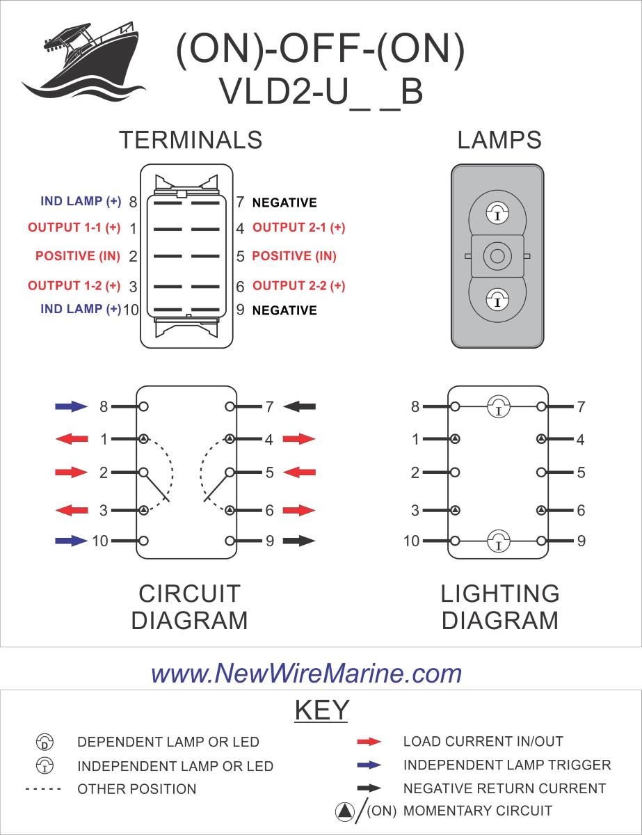
Windlass Illuminated Rocker Switch | Contura V - backlit ... from newwiremarine.com I hope this helps anyone who reads it. Two additional switches have been inserted. Feb 07, 2011 · in this diagram, the number 7 is exactly where the toggle switch is to turn wireless radio on/off. The power source comes from the fixture and then connects to the power terminal. 1 x 3.3 mω resistor (1/4 watt) 1 x 1 mω resistor (1/4 watt) 1 x bulb with holder (regular or cfl) 1 x 5v relay module (if relay module is not available, then you need the following components) 1 x 5v. The wiring diagram above is similar to the ones shown earlier. 1 x 555 timer ic; The level switch is the device in the tank of the toilet that turns the water off once.
The circuit diagram for the touch on and off switch circuit is shown in the below image.
That is each time the button is pressed the output turns on if it is presently off and off if it is on. One switch connects (or disconnects) the white wire on the bottom terminal. You will see that there is a hot wire that is then spliced through a switch and that then goes to the hot terminal of the light. Feb 07, 2011 · in this diagram, the number 7 is exactly where the toggle switch is to turn wireless radio on/off. Aug 04, 2017 · circuit diagram. The main operation of this device is to make or break contact with the help of a signal without any human involvement in order to switch it on or off. In the following diagram, x designates a closed circuit (energized or on) for a particular selector switch position, and o to designate an open circuit (not energized or off). Rocker switches are common components in many different types of electronic circuits that allow power to be turned on or off. A level or float switch is a device used to detect the height of liquids and solids. Two additional switches have been inserted. Maybe this post was a little overkill, but i was about to tear my hair out trying to figure out why my darn wireless wasn't working. The circuit diagram for the touch on and off switch circuit is shown in the below image. Level switches can be found anywhere from residential units to industrial plants, as seen in figure 8.