Home
› Wall Switch Wiring Diagram / How To Wire A Light Switch Hot Fantastic Wiring, Lights To, Switch Diagram Beautiful Single ... / Sometimes it is handy to have an outlet controlled by a switch.
Wall Switch Wiring Diagram / How To Wire A Light Switch Hot Fantastic Wiring, Lights To, Switch Diagram Beautiful Single ... / Sometimes it is handy to have an outlet controlled by a switch.
Wall Switch Wiring Diagram / How To Wire A Light Switch Hot Fantastic Wiring, Lights To, Switch Diagram Beautiful Single ... / Sometimes it is handy to have an outlet controlled by a switch.. Connect the black wire from the ceiling to the black wire from the fan. Connect the white wire from the ceiling to the white wire from the fan. You are able to discover this manual easy to use as well as very inexpensive. These electrical wiring diagrams show typical connections. The grounding conductor in the cable is not shown in order to simplify the diagram.
Connect the black dimmer wire to your tagged common wire and remove the electrical tape. You are able to discover this manual easy to use as well as very inexpensive. With easy to follow diagrams and instructions, you can have that convenience in no time. Codes for correct installation of evaporative cooler, switch and wall switch box, correct wiring procedures and effective grounding. Twist the ends together clockwise and cap them using a wire connector nut.
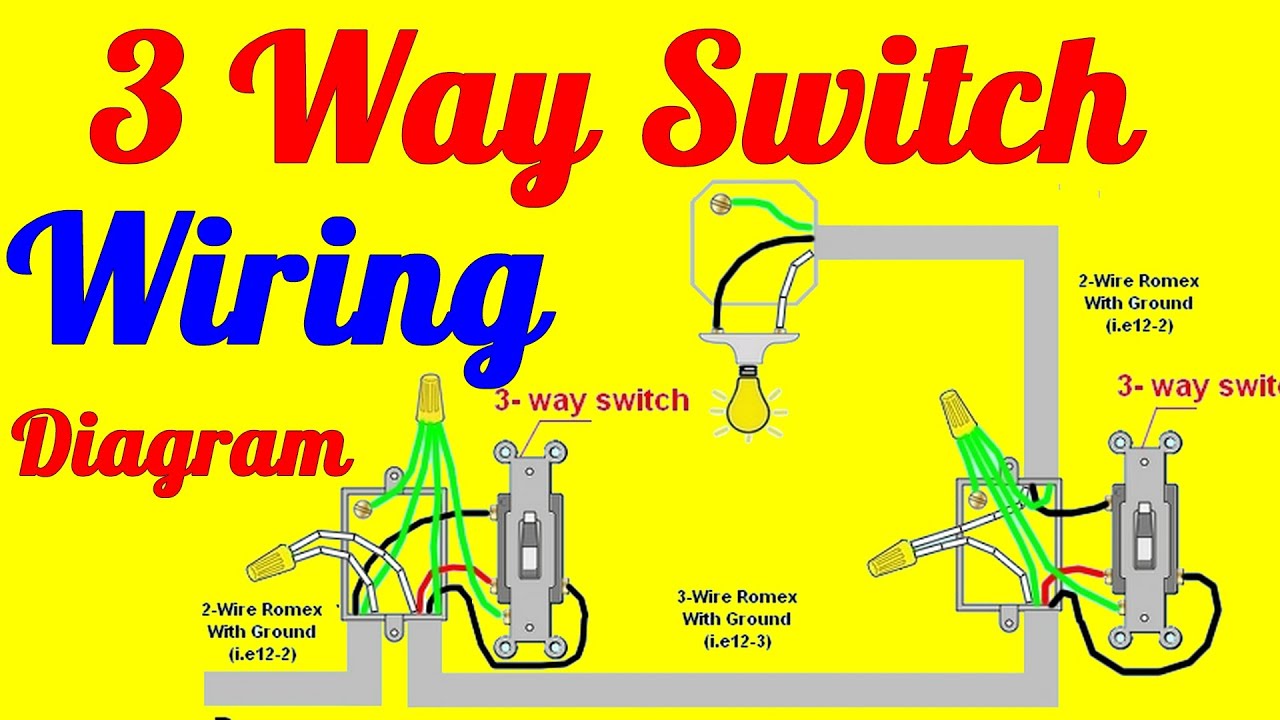
Ceiling Fan Wiring Diagram Red Wire : Hunter Ceiling Fan Switch Wiring Diagram - Atkinsjewelry ... from lh6.googleusercontent.com Similarly, a switch with a pilot that monitors the circuit to the fixture or outlet controlled by the switch is not only convenient, it may also prevent an accident caused by a failure in the circuit. The switch leg brings power to the fixture when the switch is turned on. Need help wiring a 3 way switch? The first component is symbol that indicate electrical component from the circuit. Another thing that you will see a circuit diagram would be traces. The other terminal is for a second hot wire, called a switch leg, that runs only between the switch and the light fixture. Sometimes it is handy to have an outlet controlled by a switch. As we power this circuit, electricity will flow through the hot wire over to the second switch.
A 2 1/8″ deep ceiling fan box must be used for the above ceiling fan installation.
If the wall panel only has one switch. Light switch wiring diagram depicting the electrical power from the circuit breaker panel entering the wall switch electrical box and then going to two ceiling lights via a two conductor cable. Codes for correct installation of evaporative cooler, switch and wall switch box, correct wiring procedures and effective grounding. With these diagrams below it will take the guess work out of wiring. March 31, 2018 by headcontrolsystem collection of well pump pressure switch wiring diagram. These electrical wiring diagrams show typical connections. Another thing that you will see a circuit diagram would be traces. Switched outlet wiring diagram depicts the electrical power from the circuit breaker panel entering the switched electrical receptacle outlet box where a two wire cable goes to the switch and another two wire cable feeds power to another outlet that is live at all times. Step by step instructions on how to wire a switched outlet. Take a closer look at a 3 way switch wiring diagram. Need help wiring a 3 way switch? It may, in some cases, even return to the wall from the second switch. This switch is recommended for 120 volt applications only.
The source is at the outlet and a switch loop is added to a new switch. Connect the ground wire from your dimmer to a green or bare copper wire in the wall box. There are two things that will be found in almost any ceiling fan wall switch wiring diagram. This might seem intimidating, but it does not have to be. Connect the white wire from the ceiling to the white wire from the fan.
3 Way Switch Wiring Diagrams How To Install - YouTube from i.ytimg.com You can always depend on wiring diagram being an important reference that may help you save. The source is at the outlet and a switch loop is added to a new switch. The wiring diagram above shows how switched outlets are often wired. Switched outlet wiring diagram depicts the electrical power from the circuit breaker panel entering the switched electrical receptacle outlet box where a two wire cable goes to the switch and another two wire cable feeds power to another outlet that is live at all times. As we power this circuit, electricity will flow through the hot wire over to the second switch. Before you purchase a smart light switch, you'll need to figure out the type of switch you need. With easy to follow diagrams and instructions, you can have that convenience in no time. A wiring diagram is a simplified traditional photographic representation of an electric circuit.
As we power this circuit, electricity will flow through the hot wire over to the second switch.
You are able to discover this manual easy to use as well as very inexpensive. If you need multiple lights attached to this system, just connect them together (white wire to white wire and black to black). A wiring diagram is a simplified traditional photographic representation of an electric circuit. There are too many wires for a standard 1 1/2″ deep electrical box. You can always depend on wiring diagram being an important reference that may help you save. A 2 1/8″ deep ceiling fan box must be used for the above ceiling fan installation. This switch is recommended for 120 volt applications only. Pick the diagram that is most like the scenario you are in and see if you can wire your switch! The grounding conductor in the cable is not shown in order to simplify the diagram. There are two things that will be found in almost any ceiling fan wall switch wiring diagram. If the wall panel only has one switch. This wiring diagram illustrates adding wiring for a light switch to control an existing wall outlet. With these diagrams below it will take the guess work out of wiring.
Cap the blue wire coming from the fan by itself with a wire nut as it is not needed when wiring for a single wall switch. Learn your existing wall switch and wiring setup. Similarly, a switch with a pilot that monitors the circuit to the fixture or outlet controlled by the switch is not only convenient, it may also prevent an accident caused by a failure in the circuit. As it goes through the red traveler, it will stop at switch number one. A circuit is usually composed by many components.
Wiring Diagrams For Outlet Switch And Light from i0.wp.com Step by step instructions on how to wire a switched outlet. Cap the blue wire coming from the fan by itself with a wire nut as it is not needed when wiring for a single wall switch. This might seem intimidating, but it does not have to be. Mar 09, 21 09:56 pm. Connect the black dimmer wire to your tagged common wire and remove the electrical tape. A 2 1/8″ deep ceiling fan box must be used for the above ceiling fan installation. This is commonly used to turn a table lamp on and off when entering a room. Codes for correct installation of evaporative cooler, switch and wall switch box, correct wiring procedures and effective grounding.
The other terminal is for a second hot wire, called a switch leg, that runs only between the switch and the light fixture.
As it goes through the red traveler, it will stop at switch number one. This diagram is a basic schematic and is not intended to represent all. As we power this circuit, electricity will flow through the hot wire over to the second switch. March 31, 2018 by headcontrolsystem collection of well pump pressure switch wiring diagram. These electrical wiring diagrams show typical connections. Mar 09, 21 09:56 pm. Twist the ends together clockwise and cap them using a wire connector nut. The neutral from the source is spliced through to the switch box using the white wire and in this diagram, the white wire is capped with a wire nut. The black wire from the switch connects to the hot on the receptacle. Wiring diagram 3 way switch with light at the end in this diagram, the electrical source is at the first switch and the light is located at the end of the circuit. This diagram illustrates wiring for a 4 way circuit with the electrical source at the light fixture and the switches coming after. Want to turn a lamp on with a light switch? Here a receptacle outlet is controlled with a single pole switch.