Home
› Lighting Circuit Wiring Diagram Uk / Light wiring diagrams | Light fitting : Electronic ballast has six ports, two ports out of six.
Lighting Circuit Wiring Diagram Uk / Light wiring diagrams | Light fitting : Electronic ballast has six ports, two ports out of six.
Written By
andrea
Wednesday, February 24, 2021
Edit
Lighting Circuit Wiring Diagram Uk / Light wiring diagrams | Light fitting : Electronic ballast has six ports, two ports out of six.. So, before we get stuck in to some wiring diagrams, start here to make sure you keep yourself safe. Typical house wiring diagram illustrates each type of circuit: The following circuit show how this may be done by adding a simple voltage follower. Ring, or ring final circuit (rfc). This is represented by drawing blobs on the point where they are shorted.
Ring, or ring final circuit (rfc). Lighting wiring diagrams, ceiling rose wiring diagrams, 2 way switching, 3way switching, types of light switch. The light wiring diagram shows how the live feed from the consumer unit (fuse board, shown in blue. One device may be connected to another through wires. How to install a single tubelight with electromagnetic ballast.
Ask The Trades - Electrical Glossary & Other Information from www.askthetrades.co.uk Turn off the lighting circuit you are modifying and ensure that nothing is live (ensure the light does not work and use a i've looked at countless shelly wiring diagrams, but for the life of me can't work out how to wire this in. In a typical new town house wiring system, we have cable colour changes. All the light wiring diagrams are available in the old and the new cable colours to avoid confusion. In complex diagrams it is often necessary to draw wires crossing even though they are not connected. The simple crossing on the left is correct but may be misread as a join where the 'blob' has been. Circuit symbols are used in circuit diagrams (schematics) to represent electronic components. One device may be connected to another through wires. It explains how to interpret circuit diagrams and wiring systems, and outlines the principles.
The light wiring diagram shows how the live feed from the consumer unit (fuse board, shown in blue.
Hi.in this video explains the 3 systems of lighting circuits used in the uk. As no starter is used in the case of electronic ballast application, the wiring diagram is slightly different. Typical house wiring diagram illustrates each type of circuit: All circuit symbols are in standard format and can be used for drawing schematic circuit diagram and layout. This is represented by drawing blobs on the point where they are shorted. One device may be connected to another through wires. Three way light switching wiring diagram. The layout facilitates communication between a wiring diagram can also be useful in auto repair and home building projects. I concentrated on particular one where all cables are connected at the switch. Basics of uk lighting circuits, connections to ceiling rose and light switch. It explains how to interpret circuit diagrams and wiring systems, and outlines the principles. The simple crossing on the left is correct but may be misread as a join where the 'blob' has been. All electrical pages are for information only!
In complex diagrams it is often necessary to draw wires crossing even though they are not connected. They are wired so that operation of either switch will control the light. Three way light switching wiring diagram. Use wiring diagrams to assist in building or manufacturing the circuit or electronic device. Lighting circuit connections can use designs as single line diagram, analytical and operating diagrams:
Wiring Diagram For Loop In Lighting from i0.wp.com They are wired so that operation of either switch will control the light. Typical house wiring diagram illustrates each type of circuit: The ground wire (yellow / green) must be connected to the clip marked with ground symbol. Turn off the lighting circuit you are modifying and ensure that nothing is live (ensure the light does not work and use a i've looked at countless shelly wiring diagrams, but for the life of me can't work out how to wire this in. This page contains wiring diagrams for household light switches and includes: In complex diagrams it is often necessary to draw wires crossing even though they are not connected. There will be a junction box before your light which has the. The simple crossing on the left is correct but may be misread as a join where the 'blob' has been.
Lighting circuit found in a house.
First let's have a look at this wiring diagram describing a lighting circuit in its most basic form House wiring diagrams including floor plans as part of electrical project can be found at this part of our website. Ceiling rose wiring diagrams are useful to help understand how modern lighting circuits are wired. Simply light circuit, selector switch lighting. Electronic ballast has six ports, two ports out of six. Wiring diagram of single tube light installation with electronic ballast. Basics of uk lighting circuits, connections to ceiling rose and light switch. Loop wiring is radial wiring in lighting circuits where junctions are made at ceiling roses with line and switched line wires. How to install a single tubelight with electromagnetic ballast. Using the same numbers for the cables as above in the ceiling rose diagrams, this is how the junction box would be wired to replicate the circuit. Solar pathway light circuit with constant voltage. Hi.in this video explains the 3 systems of lighting circuits used in the uk. Thclips.com/video/lpj_ne1jaqg/วีดีโอ.html part 3 how to wire a single pole light switch, in this video we look at how a single pole light switch works and the different ways to wire a.
Typical house wiring diagram illustrates each type of circuit: Turn off the lighting circuit you are modifying and ensure that nothing is live (ensure the light does not work and use a i've looked at countless shelly wiring diagrams, but for the life of me can't work out how to wire this in. The lights are fed from this via (generally) two circuits. All electrical pages are for information only! It explains how to interpret circuit diagrams and wiring systems, and outlines the principles.
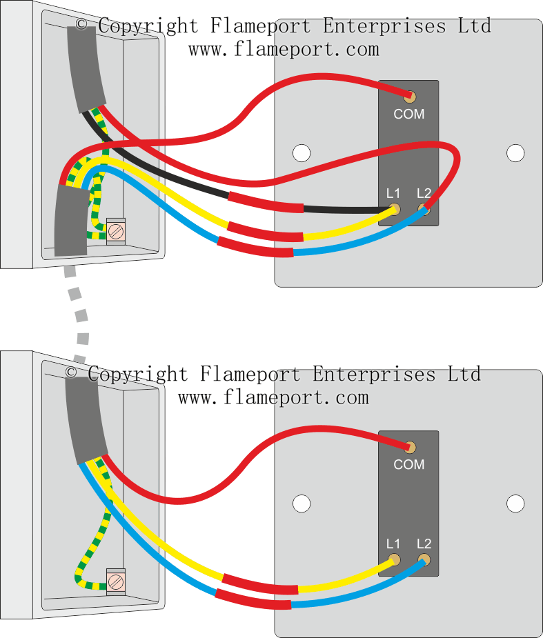
2 Way Switch Wiring Diagram Multiple Lights Uk - Wiring Diagram and Schematic Role from www.flameport.com Simply light circuit, selector switch lighting. Loop wiring is radial wiring in lighting circuits where junctions are made at ceiling roses with line and switched line wires. Circuit symbols are used in circuit diagrams (schematics) to represent electronic components. Basics of uk lighting circuits, connections to ceiling rose and light switch. They are wired so that operation of either switch will control the light. Are you able to help? The light wiring diagram shows how the live feed from the consumer unit (fuse board, shown in blue. Power comes into the house to your fuse board or consumer unit.
This is represented by drawing blobs on the point where they are shorted.
Simply light circuit, selector switch lighting. Solar pathway light circuit with constant voltage. The ground wire (yellow / green) must be connected to the clip marked with ground symbol. The following circuit show how this may be done by adding a simple voltage follower. Wring a simple lighting circuit might be an easy enough process for a qualified electrician, and with a little determination anybody with basic skills can do it. Are you able to help? Circuit symbols are used in circuit diagrams (schematics) to represent electronic components. Lighting wiring diagrams, ceiling rose wiring diagrams, 2 way switching, 3way switching, types of light switch. First let's have a look at this wiring diagram describing a lighting circuit in its most basic form One device may be connected to another through wires. Ring, or ring final circuit (rfc). In a typical new town house wiring system, we have cable colour changes. How to wire a light: