Home
› Lm2596 Module Circuit Diagram - Arduino MAG3110 magnetometer example - Arduino Learning / But how do they perform?
Lm2596 Module Circuit Diagram - Arduino MAG3110 magnetometer example - Arduino Learning / But how do they perform?
Written By
andrea
Saturday, February 20, 2021
Edit
Lm2596 Module Circuit Diagram - Arduino MAG3110 magnetometer example - Arduino Learning / But how do they perform?. Click here to check the latest version. I am working on new project which is high voltage and high current 3 phase inverter module using igbt. Input must be >1.5v higher than output. Connection diagrams and ordering information. The lm2596 operates at a switching frequency of 150 khz thus allowing smaller sized filter components than what would be needed with lower.
The lm2596 series operates at a switching frequency of 150 khz thus allowing smaller sized filter components than what would lm2596. Click here to check the latest version. I am working on new project which is high voltage and high current 3 phase inverter module using igbt. Icstation team share this lm2596 step down power module with you in details. Input must be >1.5v higher than output.
LM2596 DC-DC Step down CC/CV Adjustable Power Supply Module Converter LED Driver 760683865432 | eBay from s3-ap-southeast-1.amazonaws.com The lm2596 operates at a switching frequency of 150 khz thus allowing smaller sized filter components than what would be needed with lower. The lm2596 regulator is monolithic integrated circuit ideally suited for easy and convenient design of a step−down switching regulator (buck converter). I am working on new project which is high voltage and high current 3 phase inverter module using igbt. This module can accelerate prototyping, because you can get the voltage you need (such as 3.3v, 5v and 9v) as easy as blinking eyes. Connection diagrams and ordering information. Below is the reverse engineered circuit diagram of this particular converter board i have (key components are also marked in the picture above for reference). The lm2596 series operates at a switching frequency of 150 khz, thus allowing smaller sized filter components than what would be required with lower frequency switching regulators. Icstation team share this lm2596 step down power module with you in details.
The lm2596 operates at a switching frequency of 150 khz thus allowing smaller sized filter components than what would be needed with lower.
.datasheet, lm2596 circuit, lm2596 data sheet : I am working on new project which is high voltage and high current 3 phase inverter module using igbt. The lm2596 regulator is monolithic integrated circuit ideally suited for easy and convenient design of a step−down switching regulator (buck converter). But how do they perform? The lm2596 operates at a switching frequency of 150 khz thus allowing smaller sized filter components than what would be needed with lower. The lm2596 series operates at a switching frequency of 150 khz thus allowing smaller sized filter components than what would lm2596. Nsc, alldatasheet, datasheet, datasheet search site for electronic components and semiconductors, integrated circuits old version datasheet texas instruments acquired national semiconductor. Icstation team share this lm2596 step down power module with you in details. Input must be >1.5v higher than output. When the lm2596 is used as shown in the figure 1 test circuit, system performance will be as shown in system. This module can accelerate prototyping, because you can get the voltage you need (such as 3.3v, 5v and 9v) as easy as blinking eyes. Features • wide output voltage range • ensured 3a output load current • input voltage range up to 40v • excellent. The adjustable version can take in input voltage from 4.5v to 40v and convert it to variable voltage sourcing upto the complete circuit diagram is given below, you can often find these circuit in the lm2596 dc converter module.
The adjustable version can take in input voltage from 4.5v to 40v and convert it to variable voltage sourcing upto the complete circuit diagram is given below, you can often find these circuit in the lm2596 dc converter module. Input must be >1.5v higher than output. But how do they perform? I am working on new project which is high voltage and high current 3 phase inverter module using igbt. We will introduce the features,scope of application,diagram,and testing results.we use the digital storage oscilloscope to test the module and show you the actual testing results with pictures.you will have a full understanding of.
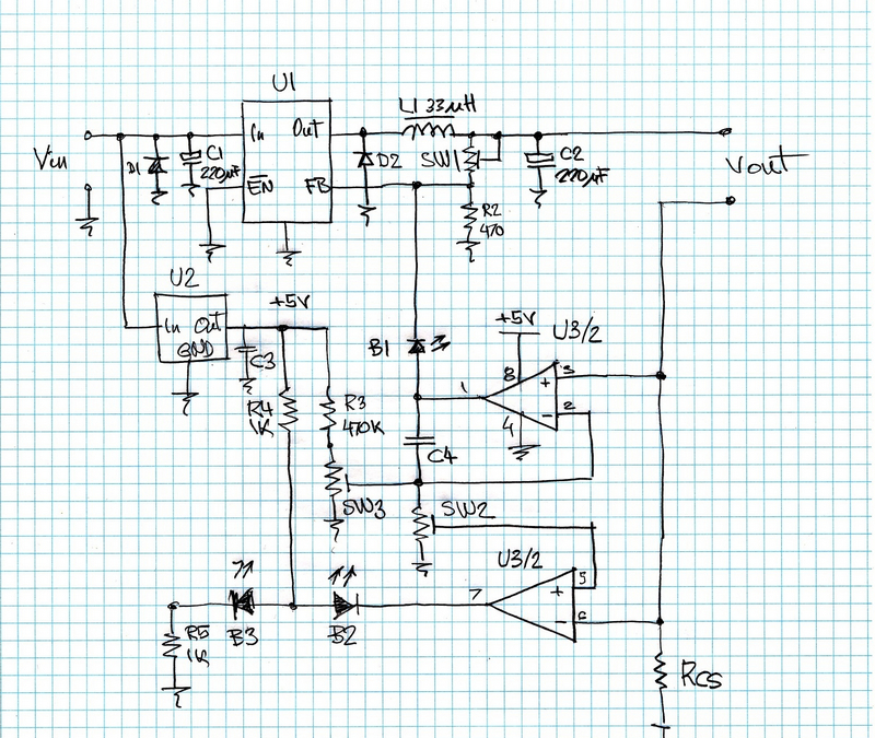
Power LED Driver from www.geocities.ws Connection diagrams and ordering information. Input must be >1.5v higher than output. But how do they perform? We will introduce the features,scope of application,diagram,and testing results.we use the digital storage oscilloscope to test the module and show you the actual testing results with pictures.you will have a full understanding of. Circuit provides very accurate reading. Below is the reverse engineered circuit diagram of this particular converter board i have (key components are also marked in the picture above for reference). .datasheet, lm2596 circuit, lm2596 data sheet : The adjustable version can take in input voltage from 4.5v to 40v and convert it to variable voltage sourcing upto the complete circuit diagram is given below, you can often find these circuit in the lm2596 dc converter module.
The lm2596 operates at a switching frequency of 150 khz thus allowing smaller sized filter components than what would be needed with lower.
This module can accelerate prototyping, because you can get the voltage you need (such as 3.3v, 5v and 9v) as easy as blinking eyes. But how do they perform? The adjustable version can take in input voltage from 4.5v to 40v and convert it to variable voltage sourcing upto the complete circuit diagram is given below, you can often find these circuit in the lm2596 dc converter module. The lm2596 operates at a switching frequency of 150 khz thus allowing smaller sized filter components than what would be needed with lower. The lm2596 series operates at a switching frequency of 150 khz, thus allowing smaller sized filter components than what would be required with lower frequency switching regulators. Connection diagrams and ordering information. Below is the reverse engineered circuit diagram of this particular converter board i have (key components are also marked in the picture above for reference). We will introduce the features,scope of application,diagram,and testing results.we use the digital storage oscilloscope to test the module and show you the actual testing results with pictures.you will have a full understanding of. Nsc, alldatasheet, datasheet, datasheet search site for electronic components and semiconductors, integrated circuits old version datasheet texas instruments acquired national semiconductor. Icstation team share this lm2596 step down power module with you in details. The lm2596 regulator is monolithic integrated circuit ideally suited for easy and convenient design of a step−down switching regulator (buck converter). Input must be >1.5v higher than output. When the lm2596 is used as shown in the figure 1 test circuit, system performance will be as shown in system.
The lm2596 series operates at a switching frequency of 150 khz thus allowing smaller sized filter components than what would lm2596. This module can accelerate prototyping, because you can get the voltage you need (such as 3.3v, 5v and 9v) as easy as blinking eyes. Click here to check the latest version. Icstation team share this lm2596 step down power module with you in details. We will introduce the features,scope of application,diagram,and testing results.we use the digital storage oscilloscope to test the module and show you the actual testing results with pictures.you will have a full understanding of.
Lm2596 Circuit Diagram - PCB Designs from i.stack.imgur.com But how do they perform? Click here to check the latest version. Circuit provides very accurate reading. The project built around lm2596adj regulator which is ideally suited for easy and convenient design here is my newly developed load cell amplifier circuit. Icstation team share this lm2596 step down power module with you in details. The lm2596 regulator is monolithic integrated circuit ideally suited for easy and convenient design of a step−down switching regulator (buck converter). The adjustable version can take in input voltage from 4.5v to 40v and convert it to variable voltage sourcing upto the complete circuit diagram is given below, you can often find these circuit in the lm2596 dc converter module. I am working on new project which is high voltage and high current 3 phase inverter module using igbt.
Icstation team share this lm2596 step down power module with you in details.
Features • wide output voltage range • ensured 3a output load current • input voltage range up to 40v • excellent. The adjustable version can take in input voltage from 4.5v to 40v and convert it to variable voltage sourcing upto the complete circuit diagram is given below, you can often find these circuit in the lm2596 dc converter module. Icstation team share this lm2596 step down power module with you in details. This module can accelerate prototyping, because you can get the voltage you need (such as 3.3v, 5v and 9v) as easy as blinking eyes. The lm2596 operates at a switching frequency of 150 khz thus allowing smaller sized filter components than what would be needed with lower. The lm2596 series operates at a switching frequency of 150 khz thus allowing smaller sized filter components than what would lm2596. The lm2596 series operates at a switching frequency of 150 khz, thus allowing smaller sized filter components than what would be required with lower frequency switching regulators. Connection diagrams and ordering information. Input must be >1.5v higher than output. Nsc, alldatasheet, datasheet, datasheet search site for electronic components and semiconductors, integrated circuits old version datasheet texas instruments acquired national semiconductor. Click here to check the latest version. The project built around lm2596adj regulator which is ideally suited for easy and convenient design here is my newly developed load cell amplifier circuit. Circuit provides very accurate reading.