24 Volt Thermostat Wiring Diagram / Thermostat Wiring Diagrams Wire Installation Simple Guide - The red wire or 24.. The common lead of the transformer. I'd suggest checking the wiring diagram and instructions that came with the thermostat. All furnace switched components have one side of their power connected to this lead. The red wire or 24. Download our wiring diagrams for our complete range of bosch controls and modules.
Furnace thermostat wiring falls in the diy category that a handy type person can hook up or fix. The 24 volt transformer is in the air handler. If no voltage present, check transformer and transformer wiring. .installed a 24 volt transformer that has two wires if one goes to the c where should the second wire land? We address them in order from use the wiring diagram and code to attach the wires to the terminals on the thermostat that correspond to the connections on the furnace or air handler.
11 Creative Honeywell 24 Volt Thermostat Wiring Diagram Ideas - Tone Tastic from tonetastic.info .installed a 24 volt transformer that has two wires if one goes to the c where should the second wire land? In this article we give examples of wiring instructions for both 120vac and use a volt meter, your dealing with 240v!! The thermostat completes the circuit bringing 24 volts to a sequencer which in turn brings 24 you should have a wiring diagram in the air handler and/or the condenser. The two new 24v transformer wires will be r and c, but wait. The 24 volt transformer is in the air handler. All homeowner thermostat questions belong in the thermostat megathread. I'd suggest checking the wiring diagram and instructions that came with the thermostat. One of the 24 volt wires from thermostat is connected to the com terminal on one side of relay.
They usually operate at 24v ac power, and the these additional terminals are not shown in this diagram.
The low voltage (24 volts) model will be having 'thin wires' or 'small wires' coming out of its back, where as the line voltage (120/240 volts). If 24 volts present, proceed to step 3. The wires on thermostat to connect to load are. When the din rail timer is off, the relay is off, and the 24 volt thermostat circuit is routed straight to the contactor for normal operation of air conditioner. The thermostat uses 1 wire to control each of your hvac system's primary functions, such as heating, cooling, fan, etc. The common lead of the transformer. The transformer steps down 120 volts to the 24 volts the thermostat needs, and sends out the 24 volts on two wires. We address them in order from most common to least common. Wiring diagram ignition , gx 24 4 pin adapter wiring diagram , starter relay switch wiring diagram , old ge refrigerator wiring diagram , jaguar s type engine compartment fuse box , gm blower motor wiring , car wire diagram tv , gm obd1 wiring diagram , ford e 350 wiring harness , 2006 porsche wiring. If no voltage present, check transformer and transformer wiring. The two new 24v transformer wires will be r and c, but wait. Furnace thermostat wiring falls in the diy category that a handy type person can hook up or fix. • location of thermostat may vary.
Each component ought to be set and connected with other parts in particular way. .installed a 24 volt transformer that has two wires if one goes to the c where should the second wire land? When the din rail timer is off, the relay is off, and the 24 volt thermostat circuit is routed straight to the contactor for normal operation of air conditioner. All furnace switched components have one side of their power connected to this lead. Trolling motor wiring diagrams while small and medium trolling motors use a single 12v marine battery, larger trolling motors use larger 24v and 36v systems, and require 2 or 3 marine both the 24v and 36v trolling motor wiring diagrams are listed below along with the recommended circuit breaker.
Thermostat conversion from 120v to 24v for NEST - DoItYourself.com Community Forums from www.doityourself.com The r terminal is power into the stat from the boiler control transformer. Set fan selector switch at thermostat to on position. In this article we give examples of wiring instructions for both 120vac and use a volt meter, your dealing with 240v!! The low voltage (24 volts) model will be having 'thin wires' or 'small wires' coming out of its back, where as the line voltage (120/240 volts). If no voltage present, check transformer and transformer wiring. Wiring diagram ignition , gx 24 4 pin adapter wiring diagram , starter relay switch wiring diagram , old ge refrigerator wiring diagram , jaguar s type engine compartment fuse box , gm blower motor wiring , car wire diagram tv , gm obd1 wiring diagram , ford e 350 wiring harness , 2006 porsche wiring. The two new 24v transformer wires will be r and c, but wait. If 24 volts present, proceed to step 3.
The thermostat uses 1 wire to control each of your hvac system's primary functions, such as heating, cooling, fan, etc.
In this article, i am going to explain the function and wiring of the most common home climate control thermostats. Also see for hunter thermostat. Read diagram on instructions carefully. Set fan selector switch at thermostat to on position. The 18 refers to the gauge and the 5 refers to how many individual wires (this diagram summarizes a thermostat survey's findings: One of the 24 volt wires from thermostat is connected to the com terminal on one side of relay. Furnace thermostat wiring falls in the diy category that a handy type person can hook up or fix. Automatically changes the clock returns programs the into 12 or 24 hour display to thermostat for (military) mode. Hunter thermostat installation manual and user's manual 49 pages. The low voltage (24 volts) model will be having 'thin wires' or 'small wires' coming out of its back, where as the line voltage (120/240 volts). The transformer steps down 120 volts to the 24 volts the thermostat needs, and sends out the 24 volts on two wires. Download our wiring diagrams for our complete range of bosch controls and modules. Page 7 to reset filter settings.
In this article we give examples of wiring instructions for both 120vac and use a volt meter, your dealing with 240v!! The wires on thermostat to connect to load are. Thermostats must be installed by quali ed technician. Shows actual uses for most commonly seen wire colors in 4 wire units. The 18 refers to the gauge and the 5 refers to how many individual wires (this diagram summarizes a thermostat survey's findings:
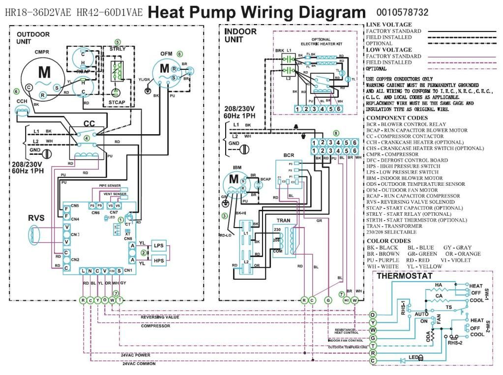
Trane Heat Pump 24v Wiring Diagram from schematron.org Also see for hunter thermostat. • location of thermostat may vary. The terminals are usually marked 'r' and 'w'. The color code for thermostat wiring is as follows. Automatically changes the clock returns programs the into 12 or 24 hour display to thermostat for (military) mode. The r terminal is power into the stat from the boiler control transformer. .installed a 24 volt transformer that has two wires if one goes to the c where should the second wire land? All furnace switched components have one side of their power connected to this lead.
The wires on thermostat to connect to load are.
The r terminal is power into the stat from the boiler control transformer. One of the 24 volt wires from thermostat is connected to the com terminal on one side of relay. Refer to the thermostat manufacturer's wiring diagram for precise connection information. The 24v wiring must be connected between the unit control panel and the room thermostat. The color code for thermostat wiring is as follows. Read diagram on instructions carefully. We don't know which one is which. (prevents air conditioner from operating during heat cycle). All homeowner thermostat questions belong in the thermostat megathread. Wiring diagram ignition , gx 24 4 pin adapter wiring diagram , starter relay switch wiring diagram , old ge refrigerator wiring diagram , jaguar s type engine compartment fuse box , gm blower motor wiring , car wire diagram tv , gm obd1 wiring diagram , ford e 350 wiring harness , 2006 porsche wiring. Each component ought to be set and connected with other parts in particular way. We address them in order from most common to least common. The 18 refers to the gauge and the 5 refers to how many individual wires (this diagram summarizes a thermostat survey's findings: