Home
› Wiring Diagram For Water Pump - Raw-water Washdown Trips Circuit Breaker - The Hull Truth - Boating and Fishing Forum - Solution direct from orangre 40 hours after lodging my questuion.
Wiring Diagram For Water Pump - Raw-water Washdown Trips Circuit Breaker - The Hull Truth - Boating and Fishing Forum - Solution direct from orangre 40 hours after lodging my questuion.
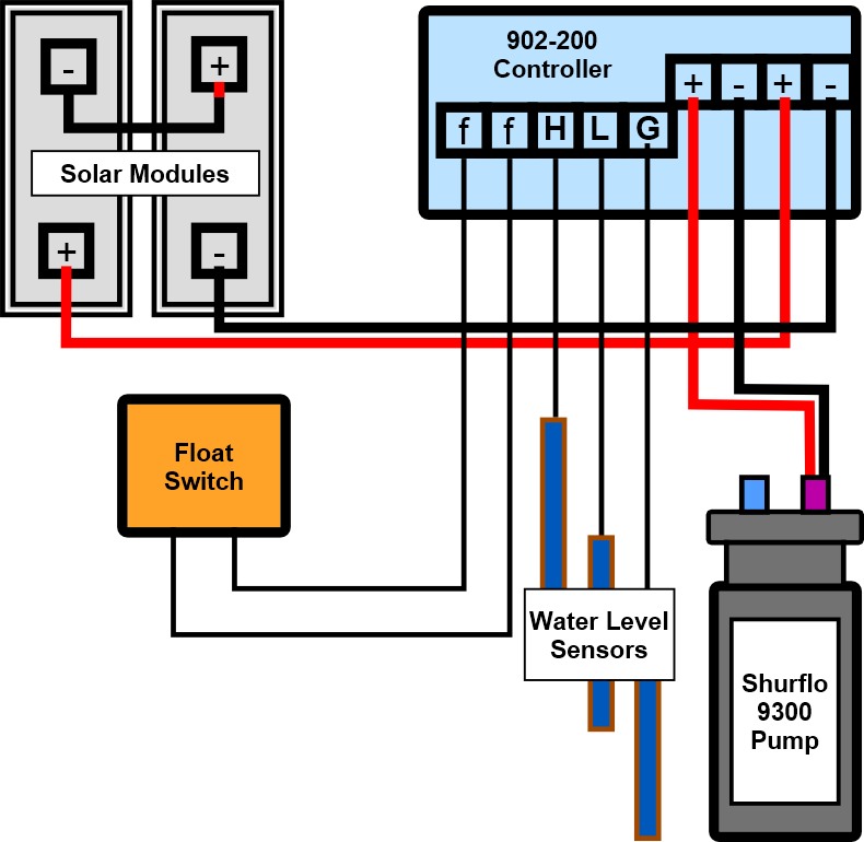
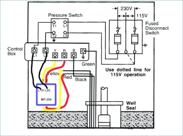
Wiring Diagram For Water Pump - Raw-water Washdown Trips Circuit Breaker - The Hull Truth - Boating and Fishing Forum - Solution direct from orangre 40 hours after lodging my questuion.. The above wiring diagram is for a rated voltage of 110 , e1' pump on e2 (u2 indicator off) amount of water for one pump cycle e2' e3 e3. I have a aquapro model jet 60sp water pump. Generally the installation of the automatic water pumps using a float level switch, and this systems is the most common method we have encountered. It reveals the elements of the circuit as streamlined forms. Two diagrams showing how to use a submersible water pump that runs on 24 volt solar panels or batteries.
It reveals the elements of the circuit as streamlined forms. They can withstand extreme amounts of heat, resist oxidation and are resistant to corrosion from environmental factors such as moisture. How to wire a pressure switch for a water pump | hunker was this helpful?people also askhow do you troubleshoot a well a wiring diagram is a streamlined standard photographic depiction of an electric circuit. Referring to the above diagrams, the first diagram shows a standard light dimmer or a fan dimmer switch circuit using a heavy duty triac bta41a/600. For example , in case a module is powered up also it sends out a signal of 50 percent the voltage and the technician.
Water Pump Diagrams - Suck Dick Videos from cdn2.bigcommerce.com How to wire a pressure switch for a water pump | hunker was this helpful?people also askhow do you troubleshoot a well a wiring diagram is a streamlined standard photographic depiction of an electric circuit. Hey guys i'm looking for the wiring diagram for the vacuum pump under the rear seat. Isolator wiring diagram this diagram shows how to wire a single pump to a pump start relay that is being controlled by two separate irrigation controllers. Automatic submersible motor controller project using 555 ic and relay. My project is water pump pressure controller. This is very simple circuit diagram of water level controller.when water tank is full then motor pump automatic switch off.automatic water motor pump controller for. Legend wiring diagram low water cutoff & alarm. February 21, 2019february 20, 2019.
February 21, 2019february 20, 2019.
For example , in case a module is powered up also it sends out a signal of 50 percent the voltage and the technician. Circuit diagram of the water pump dry run guard. Orange water pumps are for water controller for rural property. It reveals the elements of the circuit as streamlined forms. Well pump wiring diagnosis & repair: If you know where i can get some more info i'd appreiciate it. Generally the installation of the automatic water pumps using a float level switch, and this systems is the most common method we have encountered. My project is water pump pressure controller. Please note that at 113 the instructor says that the colors dont. This resistance consists of two components Great online repair source.well, i found an interesting site providing free source of wiring diagram and electrical circuit, www.wiringdiagrams21.com,hopefully can help you out of. I want to discussion about my project. I have a aquapro model jet 60sp water pump.
Power supply jumper wires cds cells. Wiring diagram and troubleshooting the soft starter for potable water well pump. Float switch connection single phase water pumpwhat is float switch?float switch is a type of level sensor a device used to detect the level of liquid. Solution direct from orangre 40 hours after lodging my questuion. Great online repair source.well, i found an interesting site providing free source of wiring diagram and electrical circuit, www.wiringdiagrams21.com,hopefully can help you out of.
Water Pump Diagrams - Suck Dick Videos from cdn2.bigcommerce.com Car alarm installation wiring diagram. Orange water pumps are for water controller for rural property. If you mean a pump wiring diagram, it depends what kind of pump you have, submersible or jetpump. They can withstand extreme amounts of heat, resist oxidation and are resistant to corrosion from environmental factors such as moisture. I am trying to wire it from 110 house wiring (2 wire, no ground) to pressure switch genebre to the pump.what i don't have any instructions or any diagram. Pump systems such as the chilled water loop pump system, the condenser water pump system, the cooling tower water pump system, and other boiler the conventional pump staging control method is the maximum flow staging method. (assume n pumps are running) Automatic submersible motor controller project using 555 ic and relay.
Both setups use two 12 volt, 60 or 90 watt solar modules wired in series to make 24 volts.
For example , in case a module is powered up also it sends out a signal of 50 percent the voltage and the technician. Orange water pumps are for water controller for rural property. Symbols that represent the constituents inside the circuit, and lines that represent the connections bewteen barefoot and shoes. I want to discussion about my project. Here is automatic water pump/ tank controller circuit diagram. The above wiring diagram is for a rated voltage of 110 , e1' pump on e2 (u2 indicator off) amount of water for one pump cycle e2' e3 e3. 1 2 3 4 5 6 7 wiring diagram : (assume n pumps are running) Bring this white neutral wire from any nearby 120volt outlet. Arduino pin 13 (named as waterpump in code) is used to turn on and off the transistor. If you know where i can get some more info i'd appreiciate it. Pump systems such as the chilled water loop pump system, the condenser water pump system, the cooling tower water pump system, and other boiler the conventional pump staging control method is the maximum flow staging method. Circuit diagram of the water pump dry run guard.
Mccb wiring diagram automatic water level pump control omron water level motor control wiring diagram tank water level control plc 2. If you mean a pump wiring diagram, it depends what kind of pump you have, submersible or jetpump. Are used extensively because of the multiple desirable properties they possess. Technically qualified personnel should install pumps and motors. I have a aquapro model jet 60sp water pump.
Water Well Pump Wiring Diagram from www.chanish.org How to wire a pressure switch for a water pump | hunker was this helpful?people also askhow do you troubleshoot a well a wiring diagram is a streamlined standard photographic depiction of an electric circuit. Arduino pin 13 (named as waterpump in code) is used to turn on and off the transistor. Basic schematic of a pumping system from a well to a storage tank. February 21, 2019february 20, 2019. For example , in case a module is powered up also it sends out a signal of 50 percent the voltage and the technician. Solution direct from orangre 40 hours after lodging my questuion. Without the use of the switch the water pump would always be on or off. Bring this white neutral wire from any nearby 120volt outlet.
1 2 3 4 5 6 7 wiring diagram :
Solution direct from orangre 40 hours after lodging my questuion. This article describes troubleshooting a submersible well pump that was causing tripped circuit breakers and that pumped water only at a slow, reduced rate and pressure. Hey guys i'm looking for the wiring diagram for the vacuum pump under the rear seat. Pump systems such as the chilled water loop pump system, the condenser water pump system, the cooling tower water pump system, and other boiler the conventional pump staging control method is the maximum flow staging method. Set the timer to turn the water heater off from 10 p.m. I want to discussion about my project. I have a aquapro model jet 60sp water pump. Transistor activated touch switch full inventory: Both setups use two 12 volt, 60 or 90 watt solar modules wired in series to make 24 volts. The information provided here is for educational purposes only. Fritzing diagram of the system. It reveals the elements of the circuit as streamlined forms. Basic schematic of a pumping system from a well to a storage tank.