Receptacle Wiring Diagrams - Dodge Ram 318 5 2l Firing Order Plug Wire Diagram Decal Sticker Ebay : Wring installation of a socket outlet receptacle.. More information wiring diagram for a 20 amp 120 volt receptacle. You don't ever want to work on basic. Wiring diagrams for ground fault circuit interrupter receptacles. Wiring diagram of gfci receptacle source connected to the line terminals on the gfci receptacle following receptacle protected connecti. 15a, 20a, 30a, 50a, 120v and 240v outlet wiring.
Electrical wiring explained wiring diagram. This article and detailed wiring diagram explains the steps to wiring the common householdwiring a receptacle : Electricians set up wiring diagrams before they start a. A wiring diagram is a simplified conventional pictorial representation of an electrical circuit. Assortment of electrical receptacle wiring diagram it is possible to download for free.
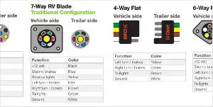
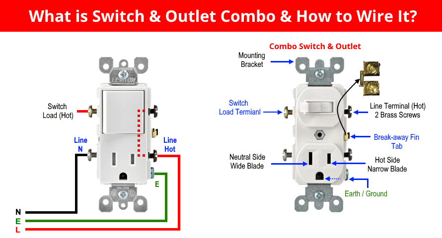
Trailer Wiring Diagram And Installation Help Towing 101 from www.curtmfg.com How to wire and install an electrical outlet receptacle? Read how to draw a circuit diagram. It ties into the common on the left switch see image below. This article and detailed wiring diagram explains the steps to wiring the common householdwiring a receptacle : Wring installation of a socket outlet receptacle. Combination switch receptacle wiring diagram for light and switch. Basic house wiring diagrams double reciptacal wiring diagram. Standard outlets can be gfci protected from a gfci outlet.
This page contains wiring diagrams for most household receptacle outlets you will encounter including:
Combination switch receptacle wiring diagram for light and switch. Wiring diagrams for ground fault circuit interrupter receptacles. Fully explained wiring instructions complete with a picture series of an installation and wiring diagrams can be found here in the gfi and light switch area here in this. 15a, 20a, 30a, 50a, 120v and 240v outlet wiring. In this diagram, both top and bottom receptacles are switched off & on. A wiring diagram is a simplified conventional pictorial representation of an electrical circuit. It ties into the common on the left switch see image below. Receptacle wiring diagram diagram data schema. More information wiring diagram for a 20 amp 120 volt receptacle. Wiring a receptacle (also referred to as an outlet) is another of those fundamental wiring skills that every this article and detailed wiring diagram explains the steps to wiring the common household. Assortment of electrical receptacle wiring diagram it is possible to download for free. The diagram will show how a standard switched duplex receptacle is wired. This page contains wiring diagrams for most household receptacle outlets you will encounter including:
Ground fault receptacle wiring outlet explained diagram with. Wring installation of a socket outlet receptacle. A wiring diagram is a simplified conventional pictorial representation of an electrical circuit. The diagram will show how a standard switched duplex receptacle is wired. In this diagram, both top and bottom receptacles are switched off & on.
Wiring Diagrams from www.how-to-wire-it.com Fully explained wiring instructions complete with a picture series of an installation and wiring diagrams can be found here in the gfi and light switch area here in this. A receptacle wiring diagram is a drawing which graphically illustrates the layout of an electrical receptacle, also known as a power outlet. With knowledge of usb receptacle intertek wiring diagram and its components might help user discovering what is wrong with the apparatus when it is not working. Read how to draw a circuit diagram. A wiring diagram is a simplified conventional pictorial representation of an electrical circuit. Learn about wiring diagram symbools. Alternate split receptacle wiring diagram. You don't ever want to work on basic.
Architectural wiring diagrams fake the approximate locations and interconnections of receptacles in this diagram, two duplex receptacle outlets are installed in the same box and wired separately to the.
Wring installation of a socket outlet receptacle. Two duplex receptacle wiring a circuit get rid of wiring. This is a standard 15 amp, volt wall receptacle outlet wiring diagram. With knowledge of usb receptacle intertek wiring diagram and its components might help user discovering what is wrong with the apparatus when it is not working. Standard outlets can be gfci protected from a gfci outlet. A wiring diagram is a simplified conventional pictorial representation of an electrical circuit. Take notice that only a. Ground fault receptacle wiring outlet explained diagram with. This page contains wiring diagrams for most household receptacle outlets you will encounter including: 15a, 20a, 30a, 50a, 120v and 240v outlet wiring. Receptacle wiring diagram diagram data schema. Wiring diagrams for receptacle outlets. You'll be able to usually rely on wiring diagram being an crucial reference that may enable you to preserve.
Electrical wiring explained wiring diagram. Wiring diagrams for receptacle outlets. Wiring a gfci outlet may vary slightly from manufacturer to manufacturer, but for the most part you can always replace a standard receptacle with a gfci receptacle. With knowledge of usb receptacle intertek wiring diagram and its components might help user discovering what is wrong with the apparatus when it is not working. You wiring it up exactly the same.
How To Wire Combo Switch Outlet Combo Device Wiring from www.electricaltechnology.org Electricians set up wiring diagrams before they start a. 15a, 20a, 30a, 50a, 120v and 240v outlet wiring. Ground fault receptacle wiring outlet explained diagram with. You don't ever want to work on basic. With knowledge of usb receptacle intertek wiring diagram and its components might help user discovering what is wrong with the apparatus when it is not working. It shows the components of the circuit as simplified shapes, and the power and signal connections between the devices. You wiring it up exactly the same. A wiring diagram is a simplified conventional pictorial representation of an electrical circuit.
You wiring it up exactly the same.
You'll be able to usually rely on wiring diagram being an crucial reference that may enable you to preserve. 15a, 20a, 30a, 50a, 120v and 240v outlet wiring. The diagram will show how a standard switched duplex receptacle is wired. A receptacle wiring diagram is a drawing which graphically illustrates the layout of an electrical receptacle, also known as a power outlet. Wring installation of a socket outlet receptacle. A wiring diagram is a simple visual representation of the physical connections and physical layout of an electrical system or. Grounded and this is a standard 15 amp, 120 volt wall receptacle outlet wiring diagram. Fully explained wiring instructions complete with a picture series of an installation and wiring diagrams can be found here in the gfi and light switch area here in this. It shows the components of the circuit as simplified shapes, and the power and signal connections between the devices. Wiring diagrams for ground fault circuit interrupter receptacles. You don't ever want to work on basic. A wiring diagram is a simplified conventional pictorial representation of an electrical circuit. Wiring a receptacle (also referred to as an outlet) is another of those fundamental wiring skills that every this article and detailed wiring diagram explains the steps to wiring the common household.