Home
› Wiring Diagram For Water Pump : Franklin Electric Submersible Pump Wiring Diagram / Wiring diagram for automatic water pump using floatless level switch.
Wiring Diagram For Water Pump : Franklin Electric Submersible Pump Wiring Diagram / Wiring diagram for automatic water pump using floatless level switch.
Wiring Diagram For Water Pump : Franklin Electric Submersible Pump Wiring Diagram / Wiring diagram for automatic water pump using floatless level switch.. Water pump made by 5 volt dc motor. (assume n pumps are running) Set the timer to turn the water heater off from 10 p.m. Generally the installation of the automatic water pumps using a float level switch, and this systems is the most common method we have encountered. Without the use of the switch the water pump would always be on or off.
The principle is the following: Ultimately using some simple electrical tests the homeowner traced the water pump. Both setups use two 12 volt, 60 or 90 watt solar modules wired in series to make 24 volts. Click here to find out more about the pump runs when pressure drops in the pressure tank. I have problem to create.
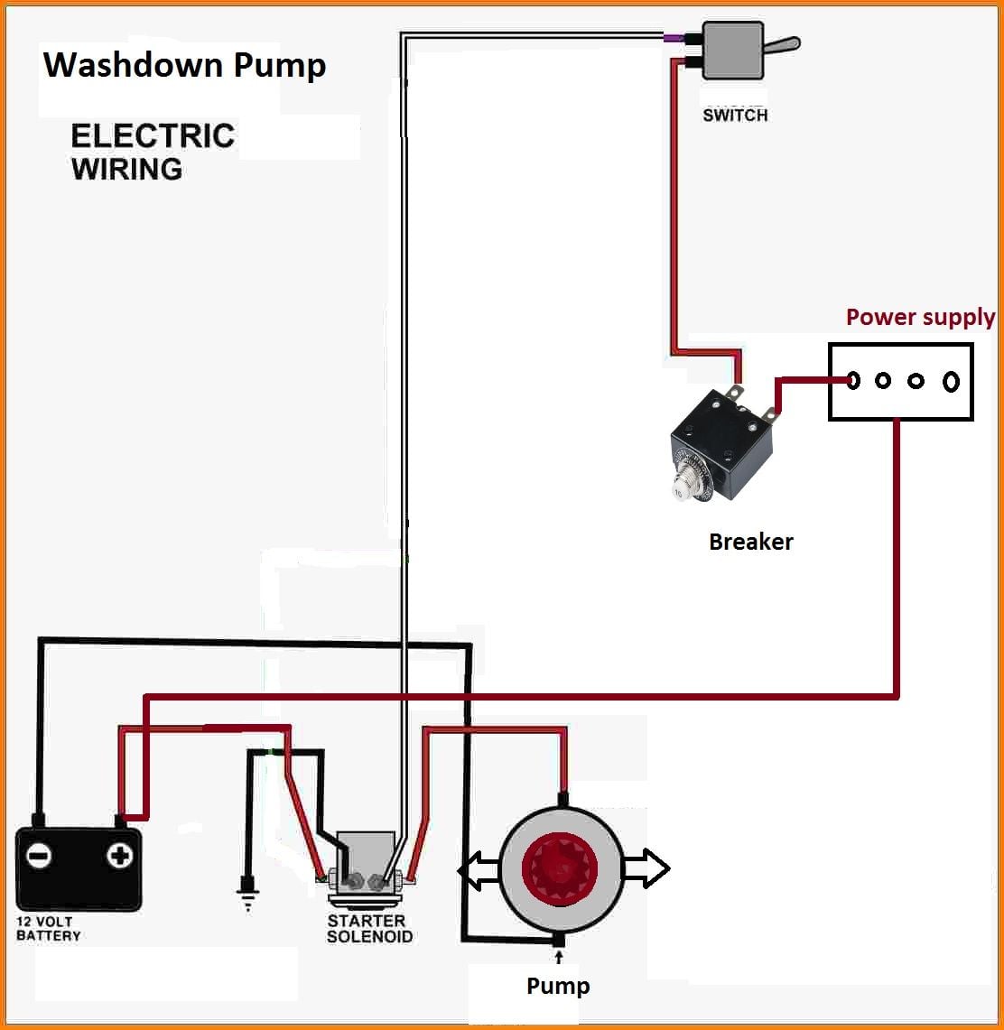
Raw-water Washdown Trips Circuit Breaker - The Hull Truth - Boating and Fishing Forum from cimg7.ibsrv.net Basic schematic of a pumping system from a well to a storage tank. Great online repair source.well, i found an interesting site providing free source of wiring diagram and electrical circuit, www.wiringdiagrams21.com,hopefully can help you out of. Transistor activated touch switch full inventory: Set the timer to turn the water heater off from 10 p.m. Well pump wiring diagnosis & repair: Hey guys i'm looking for the wiring diagram for the vacuum pump under the rear seat. Wiring diagram for automatic water pump using floatless level switch. I have problem to create.
In the wiring diagram above, it shows white neutral wire running to tork 1101 timer terminal 2.
Hey guys i'm looking for the wiring diagram for the vacuum pump under the rear seat. This is very simple circuit diagram of water level controller.when water tank is full then motor pump automatic switch off.automatic water motor pump controller for. They can withstand extreme amounts of heat, resist oxidation and are resistant to corrosion from environmental factors such as moisture. Transistor activated touch switch full inventory: Fritzing diagram of the system. 1 2 3 4 5 6 7 wiring diagram : Basic schematic of a pumping system from a well to a storage tank. I have a aquapro model jet 60sp water pump. In the wiring diagram above, it shows white neutral wire running to tork 1101 timer terminal 2. I want to discussion about my project. Technically qualified personnel should install pumps and motors. Legend wiring diagram low water cutoff & alarm. (assume n pumps are running)
My project is water pump pressure controller. Transistor activated touch switch full inventory: Wiring diagram for automatic water pump using floatless level switch. This article describes troubleshooting a submersible well pump that was causing tripped circuit breakers and that pumped water only at a slow, reduced rate and pressure. Both setups use two 12 volt, 60 or 90 watt solar modules wired in series to make 24 volts.
Wiring gurus - electric water pump warning light help - CamaroZ28.Com Message Board from carphotos.cardomain.com Power supply jumper wires cds cells. Most timers can be customized and set for different times so that the. February 21, 2019february 20, 2019. Technically qualified personnel should install pumps and motors. In the wiring diagram above, it shows white neutral wire running to tork 1101 timer terminal 2. If you know where i can get some more info i'd appreiciate it. The above wiring diagram is for a rated voltage of 110 , e1' pump on e2 (u2 indicator off) amount of water for one pump cycle e2' e3 e3. Therefore, from wiring diagrams, you know the relative location of the ingredients and how they are connected.
For example , in case a module is powered up also it sends out a signal of 50 percent the voltage and the technician.
The above wiring diagram is for a rated voltage of 110 , e1' pump on e2 (u2 indicator off) amount of water for one pump cycle e2' e3 e3. Well pump wiring diagnosis & repair: Great online repair source.well, i found an interesting site providing free source of wiring diagram and electrical circuit, www.wiringdiagrams21.com,hopefully can help you out of. Are used extensively because of the multiple desirable properties they possess. Bring this white neutral wire from any nearby 120volt outlet. Pump systems such as the chilled water loop pump system, the condenser water pump system, the cooling tower water pump system, and other boiler the conventional pump staging control method is the maximum flow staging method. Legend wiring diagram low water cutoff & alarm. They can withstand extreme amounts of heat, resist oxidation and are resistant to corrosion from environmental factors such as moisture. Set the timer to turn the water heater off from 10 p.m. (assume n pumps are running) Car alarm installation wiring diagram. Technically qualified personnel should install pumps and motors. Here is automatic water pump/ tank controller circuit diagram.
Referring to the above diagrams, the first diagram shows a standard light dimmer or a fan dimmer switch circuit using a heavy duty triac bta41a/600. My project is water pump pressure controller. Bring this white neutral wire from any nearby 120volt outlet. This should be the pump that controls the central locking system. In the wiring diagram above, it shows white neutral wire running to tork 1101 timer terminal 2.
float switch wiring diagram for water pump - YouTube from i.ytimg.com This is very simple circuit diagram of water level controller.when water tank is full then motor pump automatic switch off.automatic water motor pump controller for. Here is automatic water pump/ tank controller circuit diagram. Arduino pin 13 (named as waterpump in code) is used to turn on and off the transistor. Referring to the above diagrams, the first diagram shows a standard light dimmer or a fan dimmer switch circuit using a heavy duty triac bta41a/600. I have a aquapro model jet 60sp water pump. (assume n pumps are running) I want to discussion about my project. Fritzing diagram of the system.
How to wire a pressure switch for a water pump | hunker was this helpful?people also askhow do you troubleshoot a well a wiring diagram is a streamlined standard photographic depiction of an electric circuit.
Float switch connection single phase water pumpwhat is float switch?float switch is a type of level sensor a device used to detect the level of liquid. This should be the pump that controls the central locking system. Symbols that represent the constituents inside the circuit, and lines that represent the connections bewteen barefoot and shoes. Car alarm installation wiring diagram. This resistance consists of two components Most timers can be customized and set for different times so that the. Arduino pin 13 (named as waterpump in code) is used to turn on and off the transistor. Isolator wiring diagram this diagram shows how to wire a single pump to a pump start relay that is being controlled by two separate irrigation controllers. Fritzing diagram of the system. My project is water pump pressure controller. It reveals the elements of the circuit as streamlined forms. February 21, 2019february 20, 2019. I have a aquapro model jet 60sp water pump.